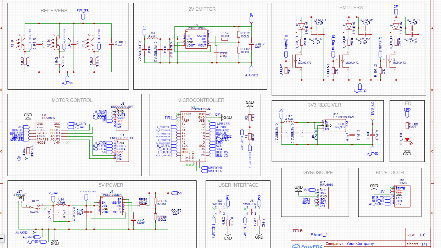
This is my first attempt at building buck converter circuits for a robot. My robot operates off a 7.4V Li-Po battery but certain voltages are needed - 5V, 3.3V, 2.0V. So I am using a buck converter from the battery voltage to 5V. Then a linear step down regulator from 5V to 3.3V and another buck converter from 5V to 2V. Since the rest of the PCB's power relies on the 5V buck converter I have been focusing on getting it to work.
The TPS82130 buck converter circuit which steps down the voltage from the battery works only for a limited time after the being soldered. Initially I had the problem that the the circuit didn't work at all but this was due to incorrect soldering and was fixed after I removed and replaced the IC. After the IC was replaced, measuring the output voltage gave 4.98V which is close enough. Then I removed the battery and put the PCB in a cardboard box. The next day when I went to check the board again, the output voltage showed roughly 0.8V. A bit of digging revealed that the resistors connected to the feedback pin were faulty in some way. After both were replaced, the output voltage once again was 4.98V.The board was once again stored in the same box. The next day when I went to work on the board and test it using an oscilloscope at school, the output voltage was measured to be 1.07V with a peak to peak difference of 26mV.
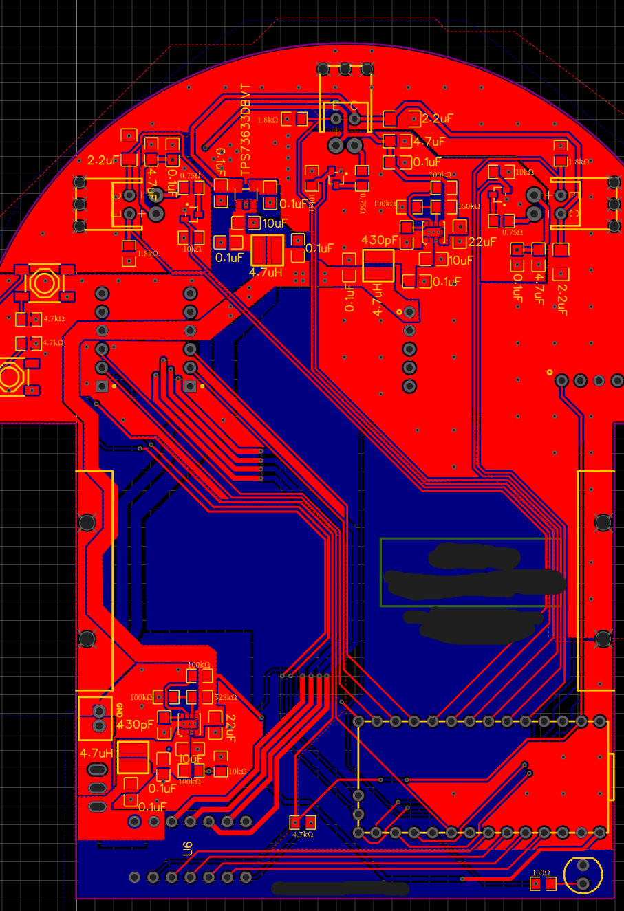
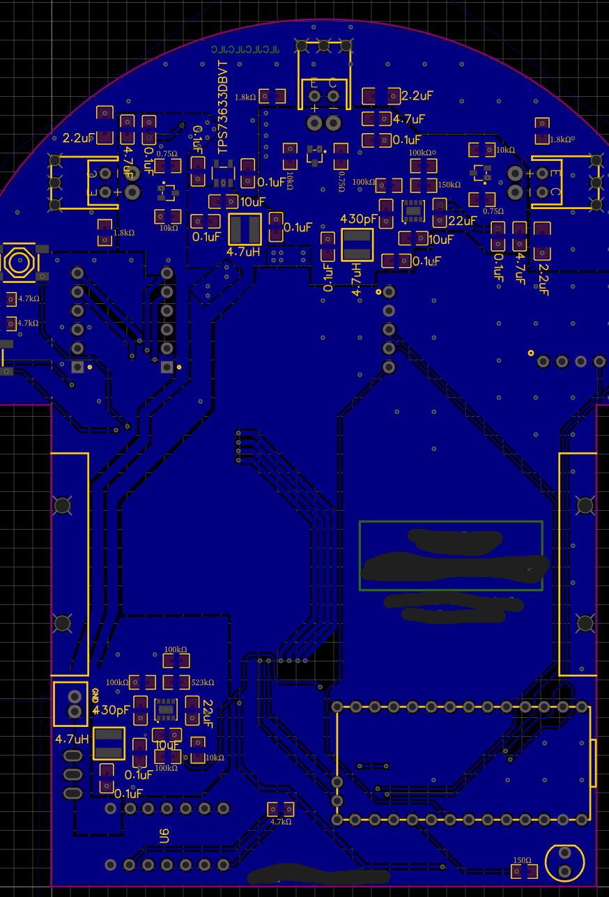
The circuit does not seem to be able to work except after it has been freshly soldered. After the feedback resistors were replaced the circuit is no longer hot and not even warm to the touch. I have not seen any smoke from any component. I have followed the datasheet and routing recommendations as far as possible. I will attach the schematic and PCB design because the problem is probably in my design. I have used resistors and capacitors with a minimum rated voltage greater than 16V and the minimum power rating of a resistor in my circuit is 125mW (523k resistor).


