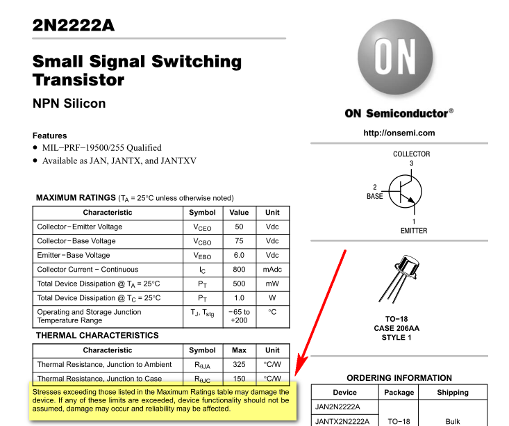
I need to know the effect of exceeding the each absolute maximum and
whether these are salvageable.
Exceeding absolute maximum ratings is always bad, that's why they are called absolute. And almost every datasheet I've ever seen states something like this:

The amount of damage can vary from a negligible (for your application) degradation of the performance of the device to a complete fireworks show. Of course it's intuitive that the largest the overstress and the longer it is applied the worse are the consequences.
Anyway, once you go beyond the maximum ratings, even for the tiniest amount and for the smallest time interval, you cannot trust the datasheet any longer. This doesn't mean it is sure 100% your device has been damaged, but it may well be. You could be lucky and have a part which is, due to manufacturing spread, more capable than the average of its kind, but there is no way to know. That is, for small over-stresses such a "stronger specimen" could survive with no damage whatsoever, but to be sure it really wasn't damaged you'd have to fully characterize the device again, i.e. you should repeat the same procedure the manufacturer does when he collects the data to compile the datasheet.
Of course, at hobbyist level such procedure is almost infeasible, so you are left with simple testing, such as checking whether the junctions of a BJT still behave as diodes using a multimeter with diode-checking capability. Even if you have a multimeter with a BJT tester this will be almost useless, since it would measure the actual hFE under some unknown conditions, and that will tell you nothing about whether the performance was better before the overstress "accident".
You could do some simple functional test, i.e. plug the BJT into some simple circuit that you know it's not critical, i.e. it doesn't rely on tight part specifications (such as using the BJT to switch on a LED), and see if it works. That will tell you that the BJT is still "usable", for some foggy definition of usable, of course.
Also, what happens in the transistor when you exceed absolute maximum
values (in the NPN junction, in terms of holes and electrons and why
the damage is permanent)
The exact process that brings a device to be damaged is a very broad area: you may want to google for "BJT failure modes" and see what pops up.
And "why the damage is permanent": why do you expect a physical object not to have limits? If I load a nylon rope too much it breaks. Neglecting how exactly the rupturing process evolves, would you expect a rope to be indestructible? The same is for electronic devices. The maximum ratings are just that: the limits beyond which the device is likely to break.

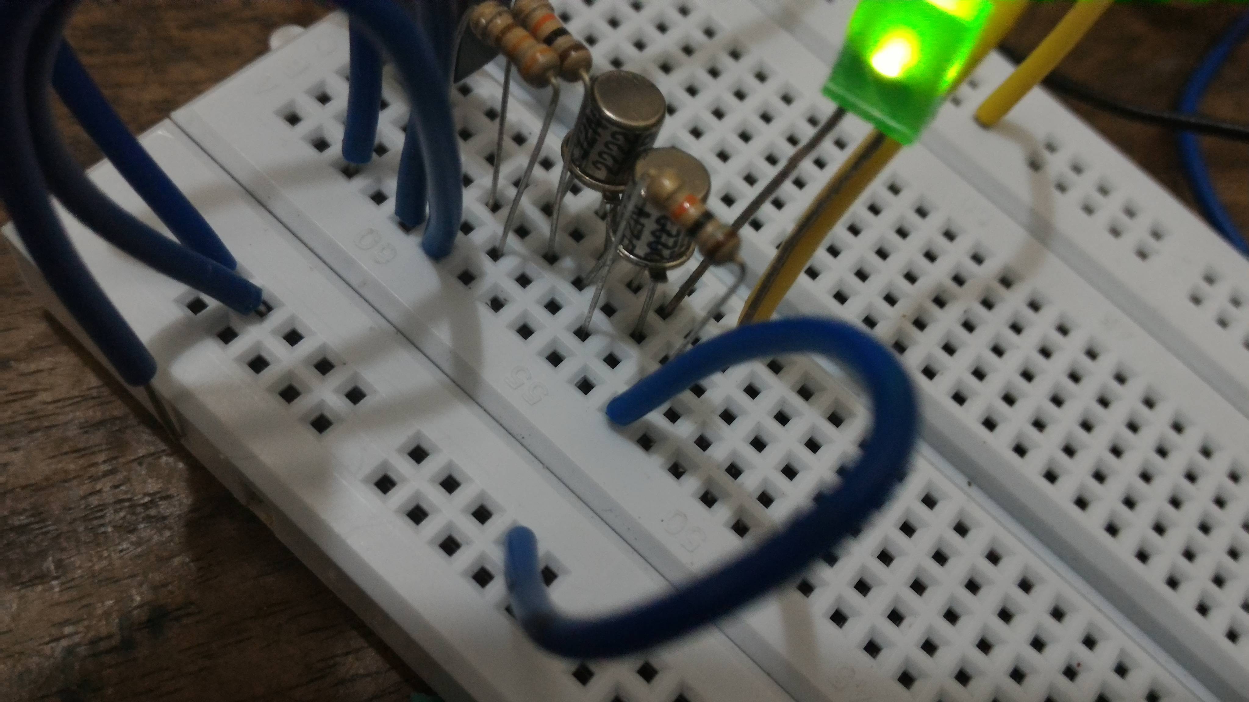
 As you can see this a transitor AND gate and yet the LED glows when only one input is high, passing the current essentially through the base and emitter. I think I fried (I think) my transistor since I'm running the transistor at the absolute maximum (this is a 2n2222a and that is a 7806 voltage regulator) bar voltage.
 ![enter image description here]](https://i.sstatic.net/4ULR2.jpg)

