2
\$\begingroup\$

I have 100 blue diffused LEDs that I want to use (not necessarily all of them) to make some kind of circuit that would likely just crawl over my wall like some vine growth coming down from the ceiling and twisting downwards to the floor, held in lots of places by pieces of tape or other adhesive. When I bought these they also came with a pack of 100 resistors that read 0.455 when I measure them on 2k scale of my multimeter (so ~500 Ω?).

I am not sure how to check the voltage for the LEDs, they do glow blue when I check them with the multimeter at 2kΩ but I assume since they are blue that they are probably meant for around 3.5 V and draw standard 20 mA. I also have a 9V battery at hand but I suppose I could get a bigger one if needed.

My question is: How should I connect these LEDs (let's assume I am using all 100)? I know the difference between serial and parallel and having them all in serial would probably take a lot of voltage right? So should I make X parallel branches with Y LEDs in each? What kind of wire should I use? Can someone help me create this circuit and also point out anything I should know by the way?

\$\endgroup\$
1
  • \$\begingroup\$ Can you give a few more details regarding what the decoration will need to look like? Just having LEDs be on is a trivial project and the only challenges are assembly and the right power delivery. The appearance will guide how many rows and columns you'll have if you don't go for the "one big string" route \$\endgroup\$
    – Funkyguy
    Commented Sep 16, 2015 at 21:26

1 Answer 1

2
\$\begingroup\$

First off, forget about powering your circuit with a battery. You'll need to get a DC power supply, although those are cheap enough on eBay. The voltage you'll need will depend on the details of the circuit you produce, and I'll get to that.

Your effect sounds cool, but be aware that you'll need a lot of independent circuits to get smooth crawling, unless you go for more sophisticated drivers than you're currently up for. Let's say you want 33 separate segments of 3 LEDs each (just for convenience and as a starting point which uses all 100, er, 99 LEDs).

First, double-check your LED operating voltage. Make a circuit like this
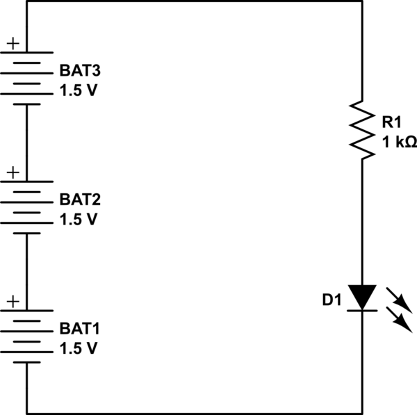
schematic

simulate this circuit – Schematic created using CircuitLab

Generally, blue LEDs don't like to have more than 5 volts applied backwards to them, which is why I suggest 3 1.5 volts batteries. Use this to tell you which pin on the LED is + and which is -, and make sure you record this. With the LED lit, use your meter to measure the LED voltage, and then the resistor voltage, which should be in the vicinity of 1 volt. The current through the resistor (and thus the LED) is 1 mA per volt across the resistor. With the LED orientation established, you can try reducing the resistor to see how bright the LED gets at various currents and voltages, and at some point you'll destroy the LED. No worries. Now you know how NOT to drive the LEDs. I'd recommend using no more than 1/2 the lethal current as your operating goal. Now you know the target LED voltage and current you want. Let's assume, as a reasonable starting point, 10 mA and 3.5 volts.

Each display segment can use 3 LEDs in series, and a single resistor to set the LED current. The voltage across the resistor should be equal to at least one LED voltage in order to keep the total current fairly stable - LED voltages will vary a bit from unit to unit. If the LED voltage is 3.5 volts at 10 mA, the total voltage across all elements will be $$V = 4 \times 3.5 = 14 volts$$, and a convenient DC power supply voltage will be 15 volts. Total current will be 33 segments times 10 mA, or 330 mA. A 15-volt, 1-amp supply will be a very good starting point.

Wire size to each segment is pretty much irrelevant, since 10 mA is very small. #24 to 26 hookup wire will do you fine. However, you'll need to get a soldering iron and some fine solder (.050 inch diameter resin-core is what you want). Also learn about tinning your iron tips.

Driving your segments is going to be a learning experience for you, and you'll need to learn something about digital logic. You can start with an Arduino and use digital outputs, but the Arduino will not directly support 33 segments. Each segment will look like
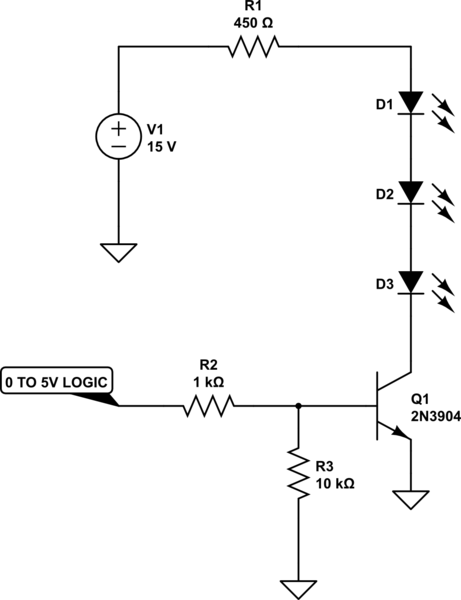
schematic

simulate this circuit

where the 450 ohms sets the LED current, and is approximate. You can use almost any value in the vicinity, and play around with different values to get the brightness you want.

\$\endgroup\$
5
  • \$\begingroup\$ I should probably point out that I went to a technical high school in Europe and as part of my computer technician education I not only learned circuitry for 3 years but also had over 100 hours of practice actually soldering and doing stuff... And I do have a soldering tool at home and other tools - I am just ashamed to say that it has been over 4 years since then I having not done anything at all with this I have more or less forgotten what I once learned... if they really teach you anything at school to begin with lol \$\endgroup\$
    – Wolf
    Commented Sep 17, 2015 at 20:21
  • \$\begingroup\$ I don't remember ever testing LEDs in this fashion and I am pretty sure at some point we would have been testing them. Isn't it the rule that the longer of the two leads is the anode (+)? Oh and why do I need the transistor? I thought having the LEDs in series with a resistor for each branch would have been enough. \$\endgroup\$
    – Wolf
    Commented Sep 17, 2015 at 20:27
  • \$\begingroup\$ Also, are you recommending me to solder all the elements together (which is what we did in school) or could I use some plastic connector parts? \$\endgroup\$
    – Wolf
    Commented Sep 17, 2015 at 20:28
  • \$\begingroup\$ I just realized you may have misunderstood my idea. I just want to light them all up and that's it. Actually making some crawling motion would be an extra bonus in the future but for now I want something basic. Can't I do it like this? i.imgur.com/muQloHj.jpg \$\endgroup\$
    – Wolf
    Commented Sep 17, 2015 at 21:04
  • \$\begingroup\$ @Wolf - 1) If you already know the orientation, you can skip the test. 2) You'll only need the transistor to interface between a logic controller. 3)Solder. Plastic will not make electrical connection. 4)Yes you can. You got it exactly right. \$\endgroup\$ Commented Sep 17, 2015 at 22:51

Your Answer

By clicking “Post Your Answer”, you agree to our terms of service and acknowledge you have read our privacy policy.

Not the answer you're looking for? Browse other questions tagged or ask your own question.