3
\$\begingroup\$

Is there a way in EAGLE CAD (Version 7) to create "sharp" traces?

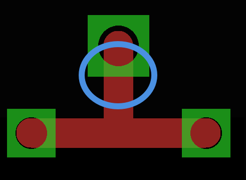
Here an image for better explanation:

enter image description here

The trace can be made wider. But if I increase the width, it looks something like this:

enter image description here

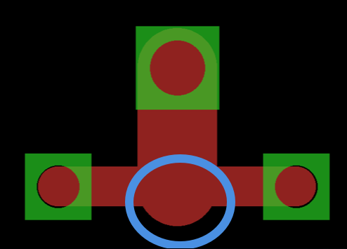
Which is not what I want. Rather I want something like this:

enter image description here

\$\endgroup\$
3
  • \$\begingroup\$ I think the first one looks better. It can be wider or it must be wider? \$\endgroup\$ Commented Sep 23, 2015 at 16:20
  • \$\begingroup\$ @PedroQuadros It can be wider. \$\endgroup\$
    – Marco
    Commented Sep 23, 2015 at 16:23
  • \$\begingroup\$ I could have sworn that older version used to use octagonal apertures for traces...can't seem to find it or do that anymore. \$\endgroup\$
    – Brad
    Commented Jan 26, 2018 at 17:25

3 Answers 3

3
\$\begingroup\$

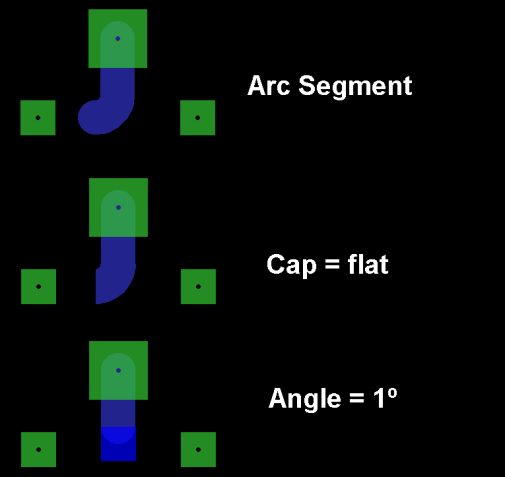
Make a small arc segment at the end of the line, then change its angle to 1° and the cap to flat. Now you can drag the 'sharp' end to a position inside the other line.

enter image description here

\$\endgroup\$
3
\$\begingroup\$

I've done this two ways:

  1. Position the wide trace's endpoint somewhere on the upper edge, not the middle, of the horizontal trace. Then use a narrower trace to make a connection from the wide trace's endpoint to the midline of the horizontal trace. The narrow connecting trace will be surrounded by copper, and so it's only there to make Eagle happy.

    Or,

  2. Draw the wide trace as you have it shown in your second image. Then, draw a polygon over the top of the wide trace, using the edges of the trace as guides. Of course, don't draw the extended radius in the polygon :) Assign the polygon to the same net name, then delete the original trace.

I can add pictures later today if this doesn't make sense. Please let me know.

\$\endgroup\$
2
  • \$\begingroup\$ hm.. so there is no real clean way of doing this in EAGLE? \$\endgroup\$
    – Marco
    Commented Sep 23, 2015 at 16:38
  • 1
    \$\begingroup\$ @d3l Not that I've found. Even Cadence OrCAD software has this same problem. Or perhaps I simply haven't found the solution yet :) \$\endgroup\$
    – bitsmack
    Commented Sep 23, 2015 at 16:51
0
\$\begingroup\$

Using round apertures for drawing traces has an advantage, the actual width of the trace is independent of the angle of the trace. When using a square aperture instead, a trace with 45 ° is wider than a trace with 0 or 90 °.

\$\endgroup\$

Your Answer

By clicking “Post Your Answer”, you agree to our terms of service and acknowledge you have read our privacy policy.

Not the answer you're looking for? Browse other questions tagged or ask your own question.