2
\$\begingroup\$

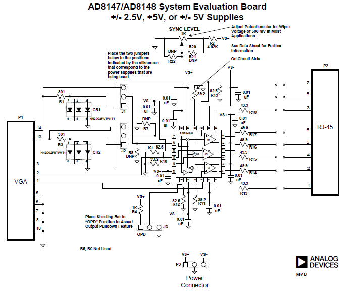
I'm working on project that requires me to convert my single ended RGB signal(VGA from PC) to differential ended RGB. I made this circuit given below the only change that I made was using a 4.7K resistance in place of R2 (4.02K).

enter image description here

I connected my VGA output from PC to connector P1 and left connector P2 open. I observed the signals at the end of my cable (The end that I shall connect to my board) and I wasn't getting proper pulses of Hsync and Vsync till I connected it to my board. I'm using a single 5V supply. So I didn't connect Vs-ve and left it open. I used three jumpers to short:

  1. Pin 1 of J1 with pin 2 of J1.
  2. Pin 1 of J2 with pin 2 of J2.
  3. Pin 1 of J3 with pin 2 of J3.

Then came the problem of observing my output signal which is differential. Now I tried looking for the procedure to observe a differential signal on an oscilloscope. I found out that :

  1. I'll be needing two channels. One will be connected to the positive output end and the other will be connected to the negative output end.
  2. I'll be connecting the grounds of my probes to each other and nothing else.
  3. I'll have to keep both channels on "AC coupling"

But when I did these three things and observed my output at R+ and R- I wasn't getting a proper output.

My questions are:

  1. Do I need to connect a load to P2 to be able to observe my output?
  2. What kind of output I should be expecting? I tried googling images of a random RGB signal but I didn't get anything that would give me an idea of what I should be seeing on the oscilloscope.
  3. Is my testing procedure correct?
  4. Do I need to connect ground on Vs-ve?
\$\endgroup\$

1 Answer 1

0
\$\begingroup\$
  1. Differential current drivers tend to require a load. This is not the case for the output drivers in AD8147, as far as I can see. Adding a load of 100 Ohms should not hurt, though and is something you can try.
  2. I would suggest a look into the AD8147 datasheet, especially Figure 31. There is an exact example how VSYNC and HSYNC are encoded onto the RGB signals. R, G and B are just your typical analog signals, so in case it is actually a random signal, you would see a random signal there.
  3. Several points:
    1. You should connect the probe grounds together and to system ground. If you don't do that, you risk your scope if there is a grounding error.
    2. You also need to configure your scope to display the difference between the two channels, i.e. go to math mode and select something like CH1-CH2.
  4. What is ve? Vs- and Ground should not be connected.

Also, make sure that J3 is in the right (as in the direction) position.

\$\endgroup\$
1
  • \$\begingroup\$ Thanks for the help! I got the encoded sync pulses as given in the datasheet. But I need to verify my ampliture values. Could you please tell me how do I measure the "fixed gain" as given in the datasheet. Datasheet says "fixed gain is 2". I think I should verify the gain as well. \$\endgroup\$ Commented Oct 15, 2015 at 6:30

Your Answer

By clicking “Post Your Answer”, you agree to our terms of service and acknowledge you have read our privacy policy.

Not the answer you're looking for? Browse other questions tagged or ask your own question.