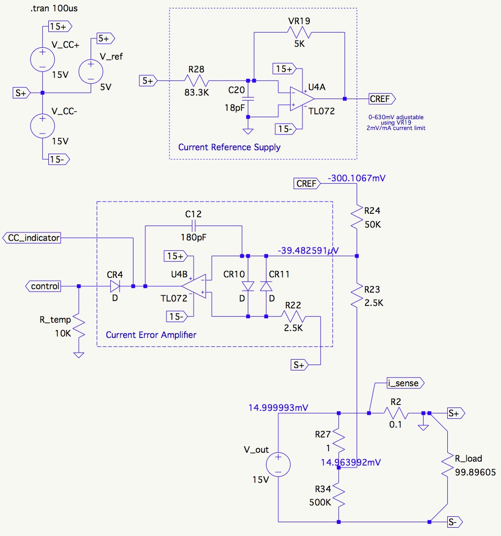
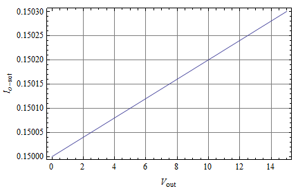
I'm studying the constant-current circuit of the Agilent E3610A 15V 30W DC Bench Power Supply. The entire schematic is at the end of the user manual, but I've redrawn the parts of interest here for clarity.
The current reference supply provides a reference voltage of 2mV/mA of current limit. Its level is adjustable via VR19, a 10-turn pot on the front panel. This part of the schematic is simplified to reduce max output and I'm showing a TL072 instead of the original LF411, but it's a pretty straightforward inverting amplifier.
The current error amplifier is also a straightforward inverting amp driving the control node. It takes its input error signal from a resistive summing point formed by R23 and R24. When the current is being limited, the value of the summing point is close to 0V. Note that S+ is ground, even though it's the positive output of the supply. The overall DC supply is an inverting amp, so somewhat counter-intuitively, the output voltage is S-.
My question is about the circuit around the current sample node labeled i_sense. A voltage of 100mV/A is developed across R2, which acts as the current sampling resistor.
Unexpectedly, to me at least, the current sample voltage is connected via a lopsided resistive divider (500k/500.001k) formed by R27 and R34.
What's up with that? Why isn't R23 connected directly to the i_sense node?
After studying it for some time, all I have is some vague guesses:
- It has something to do with behavior when the output is shorted ...
- It somehow shunts the sampling current around the current sampling resistor itself to increase accuracy
.. neither of which I'm able to make work in my head.
Can anyone help me understand? I'm pretty sure it's this way for a good reason :)


