3
\$\begingroup\$

I'm creating a power supply with an input fuse and and output fuse, and I'd like to have blown fuse indicators. However, the circuits I have found typically have set voltages and thus set resistors, which would give me varying levels of brightness, or not work at all. I'm using chassis mount fuse holders.

Input Fuse: 12V to 24V variable, but I'd like the same brightness regardless of voltage. If there's such a thing as a constant-current LED driver that's not very complex, this could work - there will always be 12V-24V on this when I'd expect the LED to be lit if the fuse was blown.

Output Fuse: 0V to 20V variable, and I'd like the LED to indicate blown even if the output voltage is 0V, but wouldn't want this voltage or current affecting the load (or requiring that there be any).

I do have a microcontroller on the board, and I could thus drive the LEDs with the digital output pins, but would prefer a solution that does not use it. Is such a circuit possible?

Essentially, I'd like to power the LEDs with a set voltage (I have 5V and 12V rails), irrespective of the voltage on the fuses themselves.

\$\endgroup\$
8
  • \$\begingroup\$ Take a step back and justify why you are using fuses in your design i.e. what are they protecting. \$\endgroup\$
    – Andy aka
    Commented Nov 14, 2015 at 11:44
  • \$\begingroup\$ Between 12 and 24V, a resistor could allow say 2-4ish mA and that will be close enough to constant brightness not to matter. \$\endgroup\$
    – user16324
    Commented Nov 14, 2015 at 13:13
  • 1
    \$\begingroup\$ As Brian says, visual brightness doesn't change much for about 2:1 current - there may be more variation between different LEDs of the same part number. The other fuse is more challenging - there is no way to detect the resistance without some voltage and thus some current flowing. If the load is (say) less than 10K (perhaps a dummy resistor across the output), a few mV output could be enough. Maybe that's 'close enough' to zero for you. There might be some conditions that would give a false response. The lamp failure tests used in automobiles (eg. for brake lamps) might be of interest. \$\endgroup\$ Commented Nov 14, 2015 at 17:44
  • \$\begingroup\$ Hmm, I'm thinking of using the microcontroller then because I'll be able to record the blowing of fuses, and I'll be able to communicate that via bluetooth. For the input fuse, I'll put in a voltage divider such that 30V in = 3V to an analog pin, then read the voltage, then read the voltage on the other side of the fuse that I'm reading. For the output fuse - any ideas? I could do the same and then read the voltage on each side of the fuse, but I couldn't tell if 0V on both sides is a blown fuse or not when the output is at 0V (perhaps I'll just disable the check while it's in this state). \$\endgroup\$
    – Ehryk
    Commented Nov 14, 2015 at 23:27
  • \$\begingroup\$ @Andyaka the fuses are on each side of my DC-DC regulator just to prevent overcurrent, what's to justify? Thoretically the regulators have their own overcurrent protection, but I'm adding in the fuses for extra protection. \$\endgroup\$
    – Ehryk
    Commented Nov 14, 2015 at 23:29

2 Answers 2

5
\$\begingroup\$

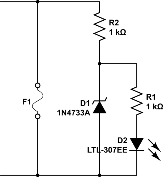
schematic

simulate this circuit – Schematic created using CircuitLab

For the input fuse, how do you feel about a couple more components? R2 and D1 form a cheap 5.1V regulator for the LED to assure a more constant brightness.

\$\endgroup\$
1
  • \$\begingroup\$ Neat! In that case, are there components readily available to do a 2V regulator, which would be exactly what the LED is after anyway (in order to use one less component)? Can you add a link to how this works as a regulator, and how I might change values to get arbitrary voltage as well as the limitations and power dissipation? \$\endgroup\$
    – Ehryk
    Commented Nov 15, 2015 at 6:02
2
\$\begingroup\$

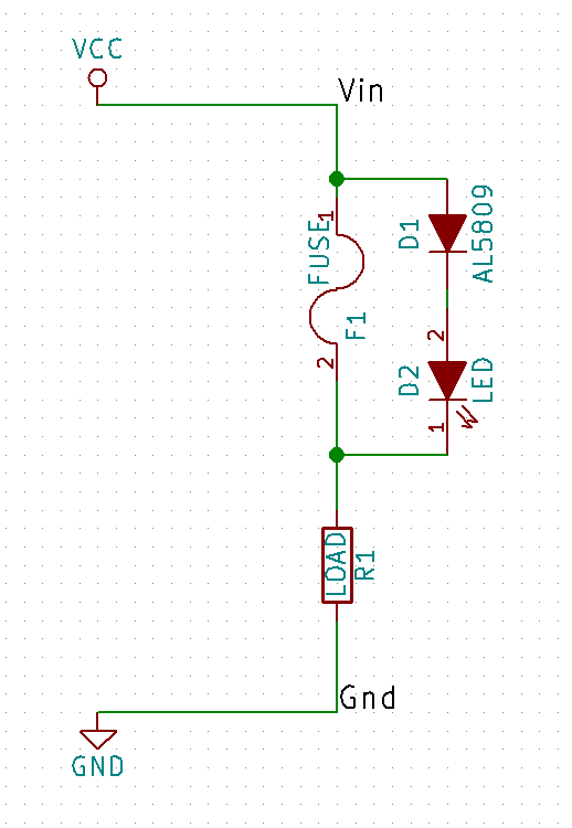
There are Constant Current Diodes such as the AL5809 built for this purpose. AL5809s can be ordered in 15mA, 20mA, 30mA, 40mA, 50mA, 60mA, 90mA, 120mA or 150mA variants, and paralleled additively.

Fuse Indication Circuit

This would be directly applicable to the input fuse, though the following components may try to operate at the reduced 20mA output of the AL5809 even with a blown fuse, which is not ideal.

This circuit could also work with the output fuse, but only when the output voltage is above 2V and with a load attached; under 2V or with no load (and no dummy load added just to meet this condition), the LED may fail to indicate a blown fuse.

\$\endgroup\$
1
  • 1
    \$\begingroup\$ @ Ehryk +1 those constant current devices are good .Do be mindful of their voltage rating .Also place an idiot resistor in series that will gracefully blow open without going on fire if the current diode failed short circuit. \$\endgroup\$
    – Autistic
    Commented Apr 9, 2017 at 0:16

Your Answer

By clicking “Post Your Answer”, you agree to our terms of service and acknowledge you have read our privacy policy.

Not the answer you're looking for? Browse other questions tagged or ask your own question.