1
\$\begingroup\$

I'm fairly new to electronics and playing around with a very simple series circuit - 2 resistors of ~220k Ohm and a 3v power supply, which I'm measuring with a digital multimeter.

If I measure the voltage across both resistors (or direct across the power supply terminals) I get a reading of 3.37 volts, but if I take a reading across the individual resistors I get 1.656 and 1.676 V (adding up to 3.332). I'm wondering what would account for the difference in total voltage? Even if the multimeter wasn't calibrated properly I'd expect it to be consistent?

Thanks!

\$\endgroup\$
5
  • 4
    \$\begingroup\$ ...also, precision ≠ accuracy. The presence of a digit on the right end of the display does not mean that digit is accurate/dependable. If you can find the manual for your meter, give it a critical read - it may surprise you, if it's an honest manual. \$\endgroup\$
    – Ecnerwal
    Commented Dec 5, 2015 at 20:56
  • \$\begingroup\$ Also see what resistance your DMM measures for each resistor and see if that helps account for some of the voltage difference. Don't forget the ohm range will also have accuracy and precision ratings like all other measurements. \$\endgroup\$
    – David
    Commented Dec 5, 2015 at 21:59
  • \$\begingroup\$ DMMs have a high but not infinite input resistance .This causes some circuit loading .You can prove this by by using some 2meg2 resistors and noticing the error increase accordingly. \$\endgroup\$
    – Autistic
    Commented Dec 5, 2015 at 22:09
  • \$\begingroup\$ @Ecnerwal resolution ≠ precision :) \$\endgroup\$
    – Armandas
    Commented Dec 5, 2015 at 22:11
  • \$\begingroup\$ @Armandas resolution ≠ precision≠ accuracy, even. \$\endgroup\$
    – Ecnerwal
    Commented Dec 5, 2015 at 22:15

3 Answers 3

3
\$\begingroup\$

I'll assume this is the circuit you`re testing
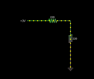
enter image description here

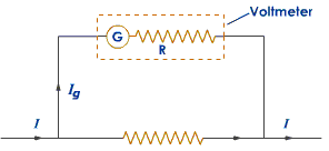
Usually a voltmeter (PMMC) type:

enter image description here

Is a galvanometer with a HUGE series resistance (Mega ohm), such that a very small amount of current pass through it whenever this voltmeter is connected in parallel with a resistance

For the circuit shown

Voltmeter is not connected yet

Voltage source is 3.3 V

Current = 0.0075 A

Load resistances = 220 Ω each

The voltage drop across each of the 220 Ω is 1.65 V = (0.0075 * 220)

BUT when you connect your voltmeter now

Assuming that: R:The voltmeter resistance = 10 MΩ And you want to measure the drop across one of your resistances

so you'll now connect your voltmeter in PARALLEL with one of these 220 Ω resistances

Now you`re adding a parallel resistance with your load of value 10 MΩ
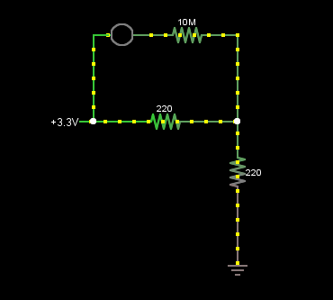
enter image description here

So the current is now not 0.0075 A since the circuit equivalent resistance is no longer the two series 220 Ω resistances only

its a combination of two parallel resistance 220 Ω,10 MΩ and a series resistance 220 Ω such that the equivalent resistance is now 439.9951 Ω (Almost less than 440)

so you'll not have the same amount of current (0.0075 A) but a slightly more amount of current in this case (0.00750008249 A) Almost 0.0075!

this in turn affects the voltage drop across each resistance by a very very small value that we usually neglect

So you'd expect a slightly smaller reading than the calculated value

Other factors also affects your reading such as

  • The source output resistance

  • Wire losses

\$\endgroup\$
2
  • 2
    \$\begingroup\$ Abdo, your answer is correct, but the OP's resistances are 220k, not 220. So the error current due to the DMM is even more pronounced than the numbers you calculated. It might be beneficial to edit your answer with the correct resistance values so the OP can understand better the actual effect he's observing. \$\endgroup\$
    – Dan Laks
    Commented Dec 5, 2015 at 22:51
  • \$\begingroup\$ Thanks for this (and the nice diagrams!). Sounds like these are fairly acceptable (or at least predictable) readings from a DMM - I'd originally assumed that even with an x% error that the errors would still be in line overall. \$\endgroup\$
    – ObTom
    Commented Dec 6, 2015 at 17:16
4
\$\begingroup\$

A typical voltage meter has about 10 MOhm input resistance, which you have to account for in your calculation. The measurement error is about 2%.

\$\endgroup\$
2
\$\begingroup\$

There are several sources of error in your measurements. One is the input resistance of the meter. Another is the full scale calibration error. We also have offset error and nonlinearity errors. Offset is normally negligible with modern meters and nonlinearity is pretty low for most (not all) meters. Nonlinearity for a 7106-based 3.5 digit meter is typically +/-0.2 count. I'll assume you have such a meter.

So, a good first order approximation of the error in reading a voltage with source impedance RS is Vr = Vx * (Rin/(Rin+Rs)*(1+a) where |a| << 1 is the full scale error for a particular range and Rin similarly is the input resistance for a particular range. In your case, two equal resistors of value R connected to a stiff voltage source, the source resistance is R/2 for the measurements across each resistor or 110K\$\Omega\$.

Looking at the total of the two measurements of closely equal resistors we have:

Vt ~= Vx * Rin/(Rin+Rs)*(1+a1). The measurement of the total is just

Vx = Vx * (1 + a2)

So Vt/Vm = Rin/(Rin+Rs)*(1+a1)/(1+a2).

To put some numbers on these errors, if the input resistance is 10M and the error on the 2V scale is -0.2% and the error on the 20V scale is +0.2%, the ratio would be 0.985. If measured on the same scale the error would be 0.989, ignoring the +/- 0.5 count uncertainty in each measurement. Your number was 3.37/3.332 =0.989, so if the assumptions were correct you got lucky in using the two different ranges- the error could have been much higher.

\$\endgroup\$

Your Answer

By clicking “Post Your Answer”, you agree to our terms of service and acknowledge you have read our privacy policy.

Not the answer you're looking for? Browse other questions tagged or ask your own question.