0
\$\begingroup\$

I bought this sensor from DFRobot to measure DC current using my 5v Trinket Pro. I followed the wiring setup and code samples from their website. Seems to be working fine once everything is setup, but I'm wondering why is it that once I disconnect the lines from the IN and OUT connections, I still would get a reading? My understanding is that I should be getting a value of 0A once I disconnect them. Am I missing something?

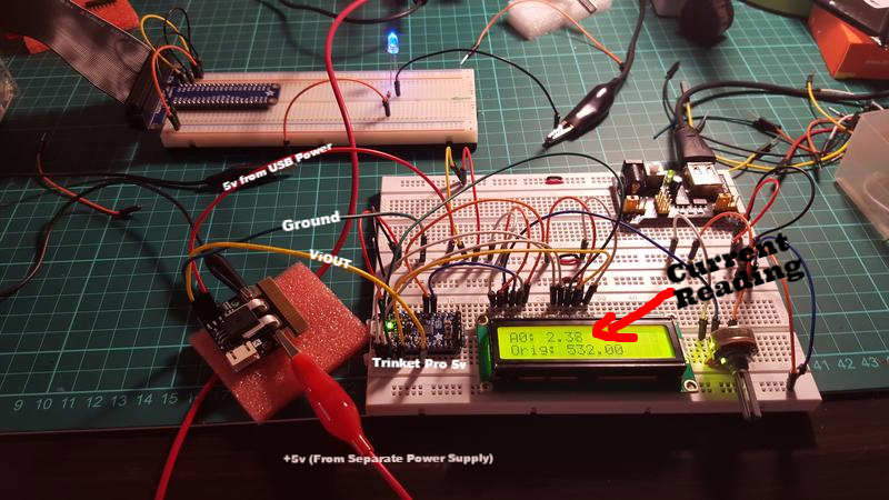
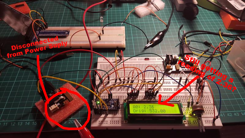
Attached are the photos of my setup below:

Lines connected to IN and OUT

Disconnected from IN, still getting a reading of 2.36A? D

Update: Here is the code from sketch

// include the library code:
#include <LiquidCrystal.h>

int RS = 3;
int EN = 4;
int D4 = 9;
int D5 = 10;
int D6 = 11;
int D7 = 12;

// initialize the library with the numbers of the interface pins
LiquidCrystal lcd(RS, EN, D4, D5, D6, D7);

const int numReadings = 30;
float readings[numReadings];      // the readings from the analog input
int index = 0;                  // the index of the current reading
float total = 0;                  // the running total
float average = 0;                // the average
float currentValue = 0;

// the setup function runs once when you press reset or power the board
void setup() {
  // set up the LCD's number of columns and rows:
  lcd.begin(16, 2);
    for (int thisReading = 0; thisReading < numReadings; thisReading++)
      readings[thisReading] = 0; 
}

// the loop function runs over and over again forever
void loop() {
    total= total - readings[index];          
    readings[index] = analogRead(0); //Raw data reading

    lcd.setCursor(0, 1);
    lcd.print("Orig: ");
    lcd.print(readings[index]);

    //Data processing:510-raw data from analogRead when the input is 0;
    // 5-5v; the first 0.04-0.04V/A(sensitivity); the second 0.04-offset val;
    readings[index] = (readings[index]-512)*5/1024/0.04-0.04;                    
    total= total + readings[index];       
    index = index + 1;                    
    if (index >= numReadings)              
      index = 0;                           
    average = total/numReadings;   //Smoothing algorithm (http://www.arduino.cc/en/Tutorial/Smoothing)    
    currentValue= average;

    lcd.setCursor(0, 0);
    lcd.print("A0: ");
    lcd.print(currentValue);
    delay(10);
}

Please bear with me as I am still new at electronics.

\$\endgroup\$

2 Answers 2

1
\$\begingroup\$

From the looks of it, you are probably getting an offset reading. If you subtract this value (reading when disconnected) and then start / stop current, does it behave according to expectation? Also do you have the opportunity to calibrate using another amp-meter? At least compare at 10, or 20 amps, whatever current your amp-meter can handle. I am also curious how are you generating 50 amps in your test setup.

On another note I can suggest an easier smoothing algorithm:

double SmoothReading, NewReading, Factor;

setup(){

Factor=30;

}

loop(){

SmoothReading = (SmoothReading*(Factor-1)+NewReading ) / Factor;

Display(SmoothReading);

}

The bigger the 'Factor' the smoother the reading, but also the slower reacting instrument.

This simple digital low pass filter served me well over the years. If you want to get real fancy you can make 2 or higher order filter. With higher order filters you get better noise rejection with faster reaction. To make 2nd order filter, you treat SmoothReading from the first filter as a NewReading for the second one and so on. For 3rd order filter I would divide Factor by 3 to get similar responsiveness.

\$\endgroup\$
2
  • \$\begingroup\$ You are correct, I am getting an offset reading. Admittedly, I missed that part on the datasheet regarding 'Quiescent output voltage' (Page 15) So that at least explains it. What I don't understand is that most of the time the offset reading fluctuates (even when no current is flowing) and gets harder for me to get an accurate reading. Is this the "noise" you are referring to where a "low pass filter" would help prevent? Sorry,I am not yet familiar with the concepts of 'digital low-pass filters' and what they are for. Would you be so kind and share some good reference materials about this? \$\endgroup\$ Commented Dec 18, 2015 at 18:59
  • \$\begingroup\$ Noise is a very complex issue, and I would start my research in Wikipedia. In the days before the internets I've learned a lot about noise studying Analog Devices datasheets for operational amplifiers. Could you provide more details about the current that you are measuring? Most of the time you can trade off speed for accuracy, and that is what low pass filtering does for you. If you need to get the accurate reading on the current that is not likely to change quickly with time, or if you are interested in average current for the last 10 seconds, I would recommend LP filter. \$\endgroup\$ Commented Dec 21, 2015 at 13:32
0
\$\begingroup\$

These sensors can measure current flow in either direction, therefore zero current produces a mid-range output voltage. Current in one direction will yield a voltage above that, and current in the other direction a voltage below.

\$\endgroup\$

Your Answer

By clicking “Post Your Answer”, you agree to our terms of service and acknowledge you have read our privacy policy.

Not the answer you're looking for? Browse other questions tagged or ask your own question.