3
\$\begingroup\$

I am using load cell, from here. Load cell specification are mentioned on the site. 5 wire coming out, its a 4 wire core shielded load cell.

I can't get the same voltage value from +Signal and -Signal.

###What I am using:

  • Using arduino nano runs on 5 V.
  • Supplied excitation voltage : 4.78 V ~(From USB).
  • Have not grounded Shield wire.(floating)(required to ground?).
  • Using AD622 ina, connected REF voltage = VCC.
  • Using MCP3551 ADC, connected -Vin Voltage = GND.

###After checking from multimeter:

  • (+ and - signal) from Load cell: reading: 2.45v. both giving the same with respect to ground.
  • Ad622 6th pin, OUT pin, gives me 4.08v at 60-70 ohms. (using potentiometer).
  • This OUT pin is attached to MCP3551 2nd Pin, .i.e +Vin.
  • Readings are coming from MCP3551 are noise data i guess, in bytecode What else I can do to detect the fault.
  • Below is code sketch

        
    #include 
    #include 
    
    #define SS 10
    
    float fRawData;
    MCP3551 MCP_ADC(SS);
    
    void setup(){
      pinMode( SS, OUTPUT );
       
      // initialize serial communication at 9600 bits per second:
      Serial.begin(9600);
      Serial.println("Setup done.");
    }
    
    float getRawData(){
      double fVar = 0;
      int i = 0;
      bool isReady = MCP_ADC.getCode();
      if( isReady ){
        Serial.print("Raw data:");
        Serial.print(MCP_ADC.byteCode, DEC);
        Serial.println();
        
      }
    }
    
    void loop(){
      getRawData();
    }

Where is the fault. What factor / point I should consider to troubleshoot this up?
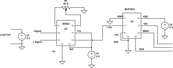

schematic

simulate this circuit – Schematic created using CircuitLab

Please check the schematic. Please ask me, if something is not clear in the picture.

\$\endgroup\$
8
  • \$\begingroup\$ AD622 ref pin to Vcc? That doesn't sound right. What is Vcc? Is it arduino bias, or USB voltage, or Vs for AD622? \$\endgroup\$
    – user16497
    Commented Apr 23, 2014 at 4:31
  • \$\begingroup\$ Can you draw some schematics? \$\endgroup\$
    – Kamil
    Commented Apr 23, 2014 at 9:09
  • \$\begingroup\$ How much noise you have? 22bit ADC is too good for circuits with potentiometers anywhere. With 22 bits you have 1uV resolution... Noise will fully cover few lowest bits. You may try to get 14-16 bit resolution. \$\endgroup\$
    – Kamil
    Commented Apr 23, 2014 at 9:13
  • \$\begingroup\$ AD622 ref pin to VCC, that is, my arduino nano is powered from USB. so i am taking USB's 5 volt to AD622 ref. \$\endgroup\$ Commented Apr 23, 2014 at 11:18
  • \$\begingroup\$ Tying Vref high is your first problem. Consult the datasheet on driving it properly. \$\endgroup\$
    – Matt Young
    Commented Apr 23, 2014 at 12:12

1 Answer 1

2
\$\begingroup\$

So far I found 1 mistake in your design.

50ohm pot is too small (Rg value)

AD622 instrumentation amplifier gain range is 2 to 1000.

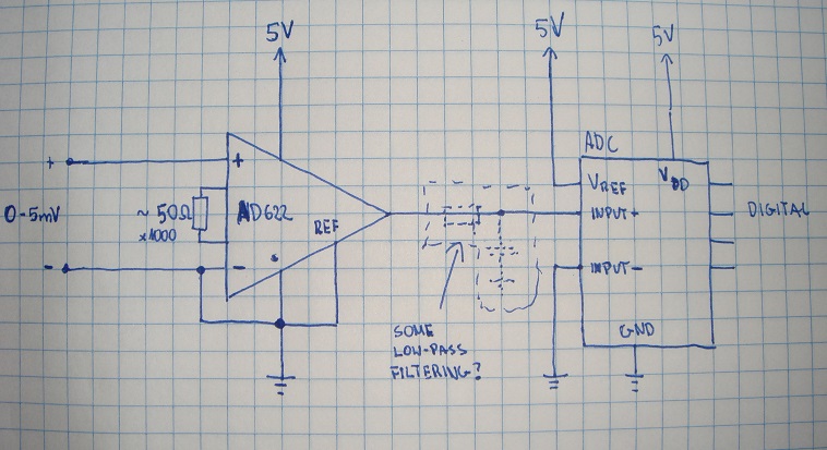
Your Ref pin at AD622 looks wrong

Typically that pin is connected to ground (for measuring positive voltages) or to Vcc/2 voltage for measuring positive and negative voltages.

Your Ref pin at ADC looks wrong

It should be connected to voltage reference (or Vcc).

enter image description here

Voltage at noniverting AD622 pin should be above or same as at inverting pin, because in-amp cant process negative differential voltage without double supply (with negative below GND).

I never had to do with such load cells, I have no idea what kind of output they have, but 4 wire connection looks like some bridge sensing.

For bridge sensing you may need negative voltage source to handle negative voltage from bridge. In-amp can't process any negative voltages at any pin if it has no negative voltage provided. I don't know if you want to measure also negative load... If you dont - maybe there is no need for negative supply.

\$\endgroup\$
8
  • \$\begingroup\$ 50 ohms, in ad622 datasheet. to gain 1000, it should be near to 50 ohms. Sorry , actually Ref pin of ADC, mcp3551 in my board, i have connected it to vcc with caps. Okay , so let me check by putting AD622 REF to ground to get positive voltages. \$\endgroup\$ Commented Apr 23, 2014 at 14:32
  • \$\begingroup\$ @anny see my updated answer. \$\endgroup\$
    – Kamil
    Commented Apr 23, 2014 at 15:04
  • \$\begingroup\$ I did make changes, but problems remains, actually, the + signal and - signal coming are not changing, means, i am not getting any variation from there while putting load. As measured from multimeter. So rest of the part are just showing values based on the coming volts from ina and adc. So problem is why +sig n - sig are not changing. Is my load cell is not good/ or wrecked? \$\endgroup\$ Commented Apr 23, 2014 at 16:27
  • \$\begingroup\$ Sig+ and sig- is probably output from bridge... That bridge is powered? Datasheet says 12V, you wrote something about 4.8V. That is your cell input voltage? \$\endgroup\$
    – Kamil
    Commented Apr 23, 2014 at 18:02
  • \$\begingroup\$ Yes, 4.8v Is my load cell excitation voltage i am providing as i have to rum my whole setup over USB only. Yes, my load cell was powered. I also tried with 9.7 V battery,what i found after is +sig and -sig are again on same voltage and each of them at 9.7 v with respect to ground. I suspect my load cell is not functioning properly. \$\endgroup\$ Commented Apr 24, 2014 at 3:43

Your Answer

By clicking “Post Your Answer”, you agree to our terms of service and acknowledge you have read our privacy policy.

Not the answer you're looking for? Browse other questions tagged or ask your own question.