1
\$\begingroup\$

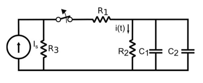
I'm working with this time dependent circuit, and i'm having troubles with some of the assignments. The following values are given R1 = 1kΩ, R2 = 2kΩ, R3 = 1kΩ, C1 = 22uF and C2 = 47uF. Is delivers 20mA, and when t=0 the switch goes from connected to disconnected. The circuit is stationary for t < 0 (when sure what that means?)

enter image description here

  • First of i shall calculate the current through R2, when T<0. Is it right when i assume i should use current division? Calculate the total Ω of the circuit, and divide by R2, times the 20mA?

  • Next, i shall calculate the voltage across C1. That one i'm uncertain about. I have found a formula V = q/C, but i can't seem to find q, the charge, or neither how to calculate what?

  • Lastly i shall find an expression for the current i(t) for t>0. Here i'm a little lost, so hoping for some guidance

Might be rather easy, but for a newbie, who have been introduced to all at once, its hard to find head and tail,

Hoping for help!

\$\endgroup\$
1
  • \$\begingroup\$ Have you been taught Laplace transforms? Or are you supposed to solve the problem using ordinary differential equations? \$\endgroup\$ Commented Dec 29, 2015 at 15:56

3 Answers 3

0
\$\begingroup\$

Typical homework problem. I think of it as two steps:

  1. Setup of Cap. Voltage via introduced energy
  2. Discharge of Cap. Through Connected Impedance

The current division between R3 and R1 + R2 in series gives you the setup current (I label it I_0) (since R3 < R1+R2, the most current should go into R3)

I0 * R2 Gives you the voltage in the node that is connecting R2, C1, C2 (I name the node n1 and the voltage V_0)

Total capacitance of two parallel caps is the sum C1 + C2 = C'

the time constant is then R2*C' = tau

Classic RC-exponential discharge curve, R2 is the current path:

V(t) = V_0 * e ^ -(t/tau)

and V = R*I gives V(t)/R2 = i(t)

easy as pie.

All these tools are easily searchable in any electronics schoolbook or the internet.

\$\endgroup\$
2
  • \$\begingroup\$ That gives a 5mA as I_0, by doing current division with R3, and R1 + R2 in series. How should i understand "setup current"? Is it simply the current running through the 3 resistors? So by multiplying 5mA * 2kΩ i get the voltage in the node (lets use n1), and by using Ohm's law, i can then calculate the current through R2? Correctly? \$\endgroup\$ Commented Dec 30, 2015 at 12:30
  • \$\begingroup\$ Sorry for late answer. I call it setup current because it happens before the event you examine (it happens before t=0, or t<0.) So it sets the initial conditions for your circuit, also the source is a current source. Thats why I find it logical to call it a "setup current", just a way of notation. But I think you got it. \$\endgroup\$
    – user55924
    Commented Jan 6, 2016 at 22:29
0
\$\begingroup\$

Most probably the phrase about the circuit being stationary for \$t<0\$ means the circuit has reached steady state. Since it is powered only by a DC current source, that means that there is no time variation of any quantity in the circuit until the switch opens.

So this allows us to determine the initial conditions of the circuit just before the switch opens: no time variations means the current in C1 and C2 is zero, hence they may be neglected in the circuit. Therefore you have the current \$I_s\$ flowing through a 2-branches current divider. First branch is \$R_3\$, second branch is the series \$R_1,R_2\$.

Applying current divider formula to obtain \$i(0-)\$ you get:

$$ i(0^-) = I_s \cdot \dfrac{R_3}{R_1+R_2+R_3} = 20mA \times \dfrac{1k\Omega}{1k\Omega + 2k\Omega + 1k\Omega} = 5mA $$

Let's tackle the voltage across the caps at \$t = 0^-\$, let's call it \$v(0^-)\$. Since the caps are in parallel to \$R_2\$, the voltage is the same, hence:

$$ v(0^-) = i(0^-) \cdot R_2 = 5mA \times 2k\Omega = 10V $$

As for the expression for \$i(t)\$ after the switch opens: notice that with the switch open you are left with two charged caps connected in parallel with \$R_2\$, hence the current in the resistor will be a classic exponential discharge curve. The time constant of the exponential is \$ \tau = R_2 \cdot C_{tot}\$ where \$ C_{tot} = C_1 + C_2 \$ is the total capacitance seen by the resistor. Therefore:

$$ i(t) = i(0^-) \cdot e^{-\frac{t}{\tau}} $$

\$\endgroup\$
5
  • \$\begingroup\$ imo. pure answers in numbers don't encourage thinking. \$\endgroup\$
    – user55924
    Commented Dec 29, 2015 at 16:06
  • 1
    \$\begingroup\$ @user55924 I agree, but maybe you saw my answer when I was editing it in progress. Numbers are there only after formulas and explanations, just as a complement to the reader at large (which is not necessarily the OP). \$\endgroup\$ Commented Dec 29, 2015 at 16:21
  • \$\begingroup\$ By using the current divider that way, don't i just obtain the current running through R3, and not what goes through the R1 and R2? Shouldn't i be using current divider on the R1 + R2 in series to get the current through R2, and from there easily calculate voltage, which is the equal to voltage through C1 as they are in parallel? \$\endgroup\$ Commented Dec 30, 2015 at 12:41
  • \$\begingroup\$ @EmilSkovgaard Please, review your formulas. I think you got it wrong. There are a couple variations of that formula. Anyway you can apply any variation of the formula and get the same result. \$\endgroup\$ Commented Dec 30, 2015 at 13:19
  • \$\begingroup\$ @LorenzoDonati I see. I first got the branch with R3, let's call it I_s1, and i got the other branch R1+R2, let's call it I_s2, as current in parallel are the same. So i calculate the current through I_s2 like: I_s2 = 20mA (R1+R2/(R1+R2) + R3) = 5mA which is the current through R2 Then i can calculate the voltage across R2 by I_s2*R2 = 40 V Think i got it right this time? \$\endgroup\$ Commented Dec 30, 2015 at 13:43
0
\$\begingroup\$
  1. There are many ways. I suggest following: Transform the current source with parallel resistor (Norton source) into a voltage source with series resistor (Thevenin source). Now you have a voltage source with three resistors in series which makes it very easy to calculate the current.
  2. For the stationary case you have to treat the Cs as open circuits (i.e. as insulators). You can use either the voltage divider formular or the result of 1. and apply Ohm's law to R2 to get the voltage across R2 (which is also across the Cs).
  3. Just a hint: \$V_c = q/C\$ is not enough. You need also \$\frac{dq}{dt} = I\$.
    i.e. \$I_c = C\frac{dV_c}{dt}\$.
    You'll get a (very simple) ordinary differential equation you must solve.
\$\endgroup\$

Your Answer

By clicking “Post Your Answer”, you agree to our terms of service and acknowledge you have read our privacy policy.

Not the answer you're looking for? Browse other questions tagged or ask your own question.