6
\$\begingroup\$

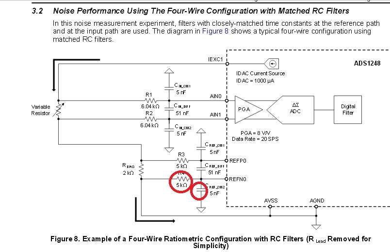
I've been scouring the web for circuits suitable for reading RTDs using ADCs. In one document from TI it is suggested that the following filter be placed on the inputs of the voltage reference pins (REFP0 and REFN0) which matches the filter on the analogue inputs, to reduce noise:

enter image description here

I haven't seen this recommendation in any other design and was wondering if it is really necessary?

My second question: suppose an RC filter would in fact help on the voltage reference pins. I don't understand why REFN0 pin also needs a filter? Wouldn't it be better if I directly connected it to GND and removed the R and C circled in red?

\$\endgroup\$

3 Answers 3

3
\$\begingroup\$

That RC is a good idea. It's worth having, especially if you will be operating in an environment with EMI.

I suspect (although the datasheet doesn't say that explicitly) that the differential REF pins are connected (through a mux) to an InAmp. One problem with InAmps is that their common-mode rejection at higher frequencies is poor. InAmp can also rectify high frequency noise at its inputs, and that manifests itself as a DC offset. To deal with that, low-pass filters are added in front of InAmp inputs to cut the high frequency components.

This is similar to what you see in fig. 5-24 of the A Designer's Guide to Instrumentation Amplifiers.

\$\endgroup\$
1
\$\begingroup\$

A filter is certainly a good idea. The converter is a delta-sigma ADC and most likely one based on a switched-capacitor topology.

In this case the reference is sampled onto a capacitor every clock cycle and should therefore have low impedance, so it is good to have a capacitor.

Due to the sampling process noise folding occurs and the filter reduces the noise bandwidth which is another reason to add the capacitor.

\$\endgroup\$
0
\$\begingroup\$

It is not necessary to have the reference filter, but may introduce more noise into your measurement. If you take it out and it makes the ADC's measurement to noisy for the requirements of your design, then leave it in. I've used this part without the radiometric current sensing, but that design used regular voltage references with no filtering. The reference input current is 30nA so that means that it is high impedance (this is assuming you also keep it within these specs low end: AVSS – 0.1, high end: REFP – 0.5 or you'll hit the protection diodes). Personally I would put the filter in, lower measurement noise is always better. And if you have your RTD on a cable, then I definitely would.

\$\endgroup\$

Your Answer

By clicking “Post Your Answer”, you agree to our terms of service and acknowledge you have read our privacy policy.

Not the answer you're looking for? Browse other questions tagged or ask your own question.