0
\$\begingroup\$

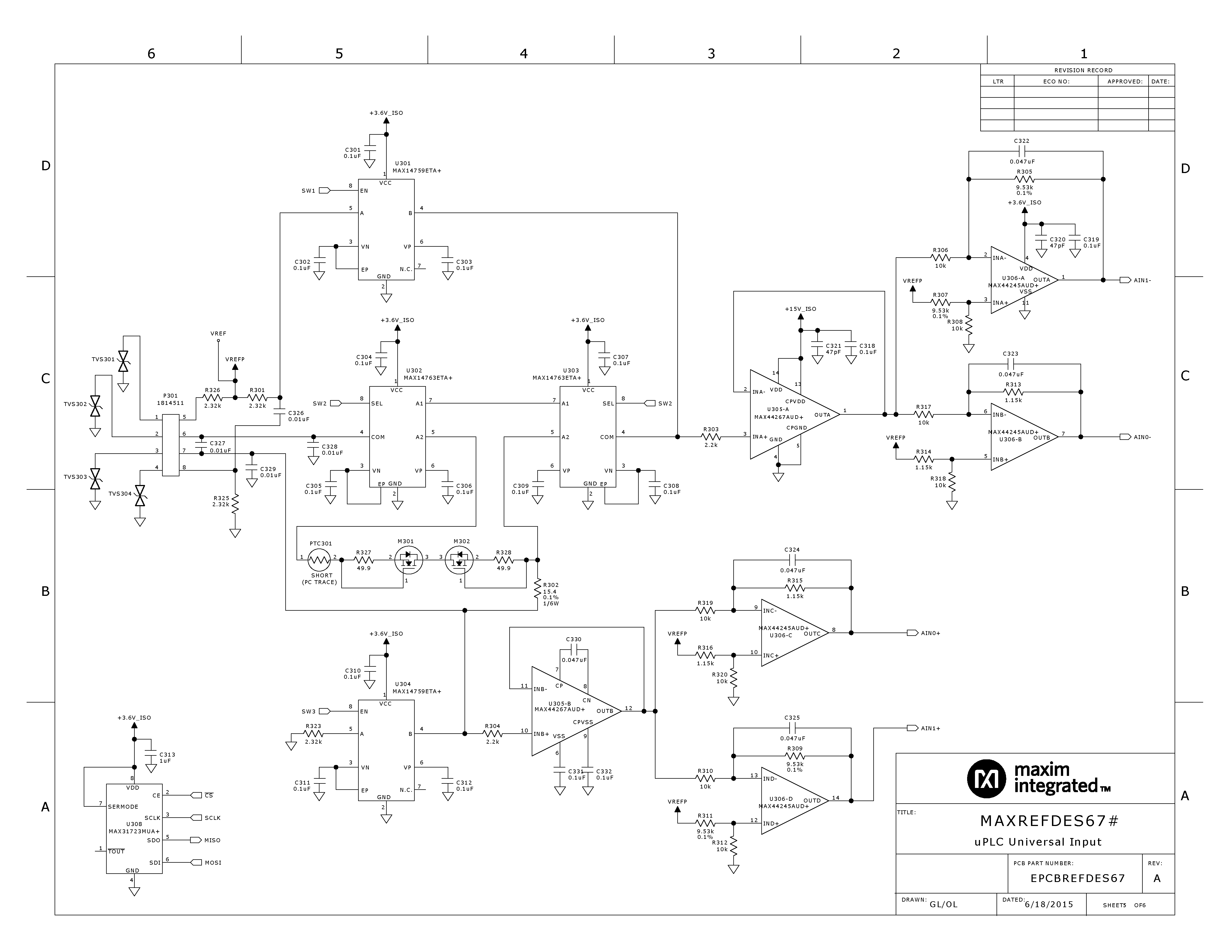
I'm trying to figure out how this universal micro-plc works: https://www.maximintegrated.com/en/design/reference-design-center/system-board/6185.html

It is supposed to read current, voltage, thermocouple's and RTDs. SChematic
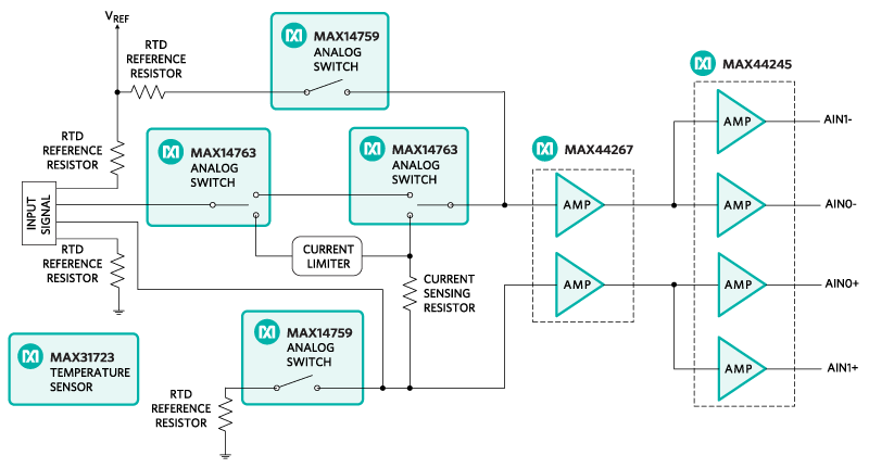
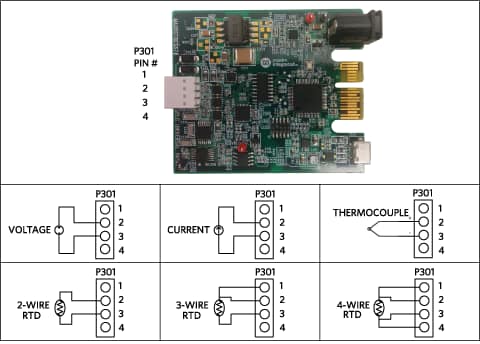
And the connection guide:

connections

I'm planning on removing the circiutry that reads voltage and current and retain the thermocouple and RTD circuits. This can be easily achieved by removing the two MAX14763 analogue switches and directly connecting input pins 2 and 3 to the amplifiers. Current limiter section and current sensing resistor need to be removed too.

Apparently the circuit is using some form of the constant voltage procedure for RTD reading, However I have no idea what to do with the two MAX14579 analogue switches because I don't understand how they are used for reading the RTD sensor and why 4 RTD reference resistors have been used. I have never seen a circuit that uses this methodology. If someone knows what is going on here or can point me to a website that explains this procedure I would be grateful.

Edit: schematic: schematic

\$\endgroup\$
7
  • \$\begingroup\$ You are talking about a circuit, resistors, certain ICs but we have no idea how it works since we don't have a schematic, how are we supposed to explain it? \$\endgroup\$
    – PlasmaHH
    Commented Apr 20, 2018 at 7:51
  • \$\begingroup\$ I'm planning on <strike>removing<\strike> destroying the circiutry that reads voltage and current and retain the thermocouple and RTD circuits. This can be easily achieved by removing the two MAX14763 analogue switches and directly connecting input pins 2 and 3 to the amplifiers. Go for it. Randomly remove components that the firmware expects to be using in ways you don't understand. Why remove anything if the board is expected to do what you want it to do? \$\endgroup\$
    – Neil_UK
    Commented Apr 20, 2018 at 8:16
  • \$\begingroup\$ @PlasmaHH Schematic added. I've already figured out how the circuit works and there is no need to go into a detailed explanation. I simply don't understand the RTD reading section with the two analogue switches and 4 resistors. \$\endgroup\$
    – hadez
    Commented Apr 20, 2018 at 8:17
  • \$\begingroup\$ So, you are trying to design an RTD amplifier from the top down. Rules: find a circuit that might be good but overly complex and reduce, reduce until you are left with just the bits you want. Is your normal job a software engineer LOL? This isn't the way to tackle the problem BTW. \$\endgroup\$
    – Andy aka
    Commented Apr 20, 2018 at 8:19
  • \$\begingroup\$ @Neil_UK Yes that is the idea. I don't need the voltage/current reading section for my work so there is no need to waste $$$ on it. \$\endgroup\$
    – hadez
    Commented Apr 20, 2018 at 8:19

1 Answer 1

1
\$\begingroup\$

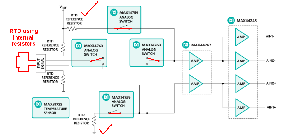
Using the internal resistors and a two wire connection: -

enter image description here

\$\endgroup\$
5
  • \$\begingroup\$ Why use the two resistors at the top and bottom of the circuit? I mean the two that are connected using analogue switches. \$\endgroup\$
    – hadez
    Commented Apr 20, 2018 at 8:29
  • 2
    \$\begingroup\$ Well, an RTD needs a series resistor and given that the InAmp is differential using two resistors makes a lot of sense common-mode-rejection wise. Bear in mind that this site isn't a discussion site. You asked a question and I gave an answer. Sure, spin-offs are allowed up to a point so that's 33% of your quota used. Think about your next question carefully and don't make it too long-winded. You might surprise yourself and figure it out along the way. \$\endgroup\$
    – Andy aka
    Commented Apr 20, 2018 at 8:34
  • \$\begingroup\$ This supports both 2 wire and 4 wire RTD connections. In 2 wire, you also measure the temperature of the connecting wires. In 4 wire the connecting wires can be removed, if you know the current, and the current measurement R lets you work that out \$\endgroup\$
    – Henry Crun
    Commented Apr 20, 2018 at 9:15
  • \$\begingroup\$ @Andyaka EUREKA ... Your reference to CMR solved it for me. It was the bottom sense resistor that was baffling me (which as you stated is used for CMR). Thanks a lot. \$\endgroup\$
    – hadez
    Commented Apr 20, 2018 at 10:20
  • 1
    \$\begingroup\$ @hadez you did good!! \$\endgroup\$
    – Andy aka
    Commented Apr 20, 2018 at 11:42

Your Answer

By clicking “Post Your Answer”, you agree to our terms of service and acknowledge you have read our privacy policy.

Not the answer you're looking for? Browse other questions tagged or ask your own question.