0
\$\begingroup\$

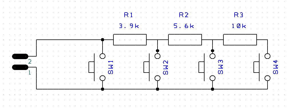
I'm looking to create a circuit which will be used to test external PCBs. One of the external circuits features four switches with three resistors in what I believe is known as a resistance ladder (or network). The schematic for this is below:

enter image description here

Could someone very kindly draw me a basic circuit which features four LEDs which illuminate depending on which switch is being operated on the external circuit? Hopefully this isn't too complicated?

I.e if SW1 is being pressed on this external circuit then LED1 illuminates on our circuit and so on.

I'd really appreciate any help or advice with this! Thank you in advance!

\$\endgroup\$
9
  • \$\begingroup\$ You could use these pushbutton switches (here) as a means to separate the leds electrically from the ladder. \$\endgroup\$
    – K. Rmth
    Commented Mar 29, 2016 at 21:58
  • 1
    \$\begingroup\$ What are your constraints? Can you use a microprocessor? This SE is not a design service, nor will most folks be motivated to do what looks like homework. What have you tried? \$\endgroup\$
    – user65586
    Commented Mar 29, 2016 at 22:02
  • \$\begingroup\$ I have no constraints other than the external circuit cannot be alterered as that's what it is. So unfortunately I cannot use different switches. I haven't tried anything as I simply don't know where to start. I'm not looking to offend people and it certainly isn't homework, I'm simply asking for some basic guidance on how to go about this, do I need to use some form of analogue to digital converter? \$\endgroup\$ Commented Mar 29, 2016 at 23:33
  • \$\begingroup\$ @jdv Unless our friend nb86 is strong with code, I doubt that a microprocessor is going to satisfy the "isn't too complicated" requirement. \$\endgroup\$ Commented Mar 30, 2016 at 0:02
  • \$\begingroup\$ @nb86, you are going to have to share more, as this is feeling like an "XY problem" if it isn't homework. What you are asking is to design the actual hard part of the circuit that connects to (1) and (2). But we don't know the voltages you are using, or the limits on what you connect to those points, or anything other than you have a bunch of switches that will behave like voltage dividers. \$\endgroup\$
    – user65586
    Commented Mar 30, 2016 at 0:56

2 Answers 2

1
\$\begingroup\$

Do some studies on LM3914 bar graph driver... This ic can be configured to lit any one of the 10 LEDs on its output line depending on the input voltage.

You only need to scale your resistors (in your ladder) properly to lit any of the desired LED in accordance to your individual push buttons.

With proper resistor choice you may design it so well where if more than one button pressed simultaneously, non of the LEDs will lit.

As its said in the comment, here we don't offer design service, but if you can pick up something from here, I'm sure there are many helping hands will guide you through the design.

Using LM3914 is easier for non-software geeks. Not everyone understand microcontrollers so well.

\$\endgroup\$
0
\$\begingroup\$

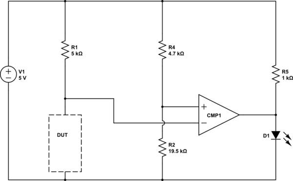
Here's a circuit that lights an LED if any of the switches is closed:

schematic

simulate this circuit – Schematic created using CircuitLab

With different values for R2, you can make one that detects if SW1, SW2, or SW3 is closed (but not SW4), one that detects if SW1 or SW2 is closed, and one that detects if SW1 is closed.

You can connect all these circuits to the junction between the DUT and R1 at the same time. So when Switch N is closed, 5-N LEDs light up. (If you re-name your switches in the opposite order, you can have N LEDs light up when switch N is closed)

If you want a different LED to light for each switch (instead of 5-N lights lit when switch N is closed), you need some digital logic connecting the outputs of these circuits to the LEDs.

Of course if you did this with a microcontroller with an ADC input, you could not only detect which switch is pushed, but you could also detect some kinds of manufacturing faults like the wrong value resistor being loaded.

\$\endgroup\$

Your Answer

By clicking “Post Your Answer”, you agree to our terms of service and acknowledge you have read our privacy policy.

Not the answer you're looking for? Browse other questions tagged or ask your own question.