3
\$\begingroup\$

This is my first ethernet circuit, and I am a noob in differential signal lines. That is why I want to learn with a "simple" circuit.

I use the reference schematics from the LAN9512 USB to Ethernet chip (100 Mb/s).

My question is with the Bob Smith terminator. The reference schematic uses a RJ45 with a transformer and the terminator included. But I want to test an external transformer (next project will be a "simple" Ethernet switch).

So, I checked other reference designs, and I found different variations for the Bob Smith circuit. Some use 51 ohm resistors, others 75 ohm... I am quite confused here.

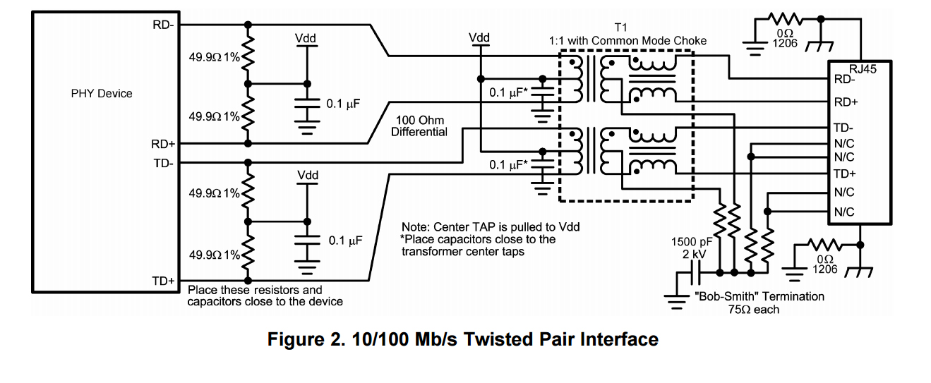
This is the terminator that I am using. It is the only one that I found that uses resistors on both sides of the transformer (I guess that is to match impedance in both sides of the transformer).

10/100 Mb/s Twisted Pair Interface

(Image source: Texas Instruments - AN-1469 PHYTER Design & Layout Guide SNLA079D)

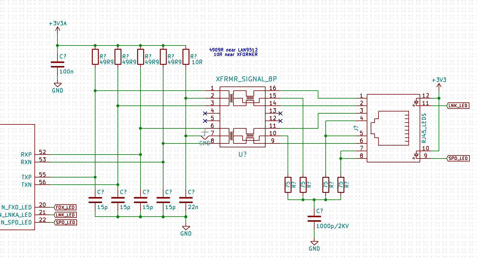
This is my schematic:

enter image description here

What do you think?

\$\endgroup\$
1
  • \$\begingroup\$ on the pin 7 of the transformer, there is a wreid gnd symbol. That is because I had it on my cursor when I took the screen shoot. Sorry for this. \$\endgroup\$ Commented Apr 20, 2016 at 11:02

2 Answers 2

2
\$\begingroup\$

The resistors on the cable side are supposed to terminate each pair being treated as one "wire". The purpose is to reduce EMI and they do not functionally affect the actual signals. The impedance is not so well defined. With 20 years of experience, the magnetics nowadays with built-in common mode chokes are effective such that those terminations do not make much difference.

The resistors on the driver side of the transformer are for terminating the differential signals. Those terminations are critical.

On your schematic, the R7 feeding the two center taps (pin 2 and 7) let open an unnecessary coupling path between the transmit and receive. I don't see why you would want that.

\$\endgroup\$
2
  • \$\begingroup\$ you mean the 10r resistor? you would let the pins 2 and 7 wired independently with a 10r resistor? I followed the reference datasheet from the lan9512 chip (and in the raspberry pi rev 2.1 datasheet)... I dont know why they connect it \$\endgroup\$ Commented Apr 20, 2016 at 10:57
  • 1
    \$\begingroup\$ Yes. I would wired them independently if a 10 ohm resistor is wanted. Although the node is heavily shunted and the common mode rejection of the device probably eliminates any real issue. \$\endgroup\$
    – rioraxe
    Commented Apr 21, 2016 at 0:13
0
\$\begingroup\$

A "Bob Smith" circuit is also necessary to prevent shorts in a Power-over-Ethernet (PoE) situation. 75ohm was standard termination when coax was used for ethernet. the capacitor is necessary to block DC from ground for PoE situations.

\$\endgroup\$
1
  • 2
    \$\begingroup\$ If you say so, then would you please describe why Bob Smith termination is necessary to prevent shorts in a PoE situation? What would cause a short if Bob Smith termination is not used? And the capacitor in above circuits is not blocking DC in a PoE situation either. The circuits above do not support PoE to begin with and would fry if PoE is forcibly applied. And no PoE source would detect the above circuits as valid PoE device and thus would not apply PoE to begin with. \$\endgroup\$
    – Justme
    Commented Aug 30, 2021 at 13:26

Your Answer

By clicking “Post Your Answer”, you agree to our terms of service and acknowledge you have read our privacy policy.

Not the answer you're looking for? Browse other questions tagged or ask your own question.