I am designing a PCB that needs two adjacent Ethernet ports, both at 1Gbps speed.
The first Ethernet port (J5) is broken out directly from the processor module (Raspberry Pi Compute Module 4).
The second Ethernet port (J6) is provided by an Intel WG82579 PCIe to Ethernet bridge. The PCIe bus is also sourced by the CM4.
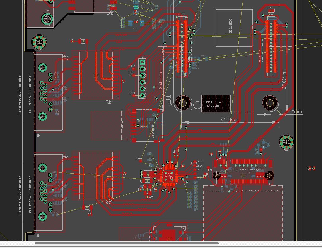
I calculated my trace and space for 100 ohm impedance matching and laid out my design to minimize vias, length match the differential pairs, and provide spacing between pairs to avoid crosstalk. My layout can be seen in the image below:
I'm quite happy that I have been able to keep almost 100% of the high speed differential routing on the top layer (red) of the PCB. My goal is to keep the bottom layer as low-noise as possible so I can put analog audio circuitry there.
However, as I have been reviewing my work, I have several concerns:
- Copper under magnetics. I have seen multiple application notes recommending that no copper, traces or GND planes, should extend beneath the Ethernet magnetics. I am currently violating that rule in order to route the Ethernet without using vias. Would it be better to use vias and remove the traces beneath the Ethernet magnetics? (T1 and T2 in image) To do this, I'd need to add vias to basically all of my Ethernet traces.
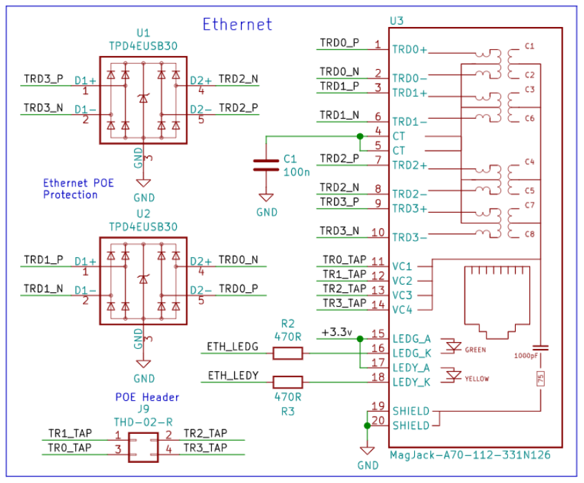
- Grounding. I based my GND scheme on what I found in the Raspberry Pi CM4 IO Board reference design. The reference design does not have a separate GND plane for the isolated side of the Ethernet port, and it allows the GND plane to extend beneath the Ethernet port. However, their design uses an RJ45 connector with integrated magnetics. My design uses separate components for the magnetics and the RJ45. Should I implement separate chassis GND planes for each Ethernet connector? Or, just leave the area under the Ethernet connectors as a copper-free area?
RPi CM4 IO Board reference schematic section:
Full schematic link here


