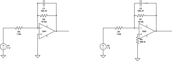
The resistor you see in some schematics is when the op-amp is a bipolar device. It will have significant input bias currents compared to a FET type op-amp. Those bias currents form an error voltage due to the external resistors. If the same net value of resistance is placed in both inputs those error voltages largely cancel out.
So, in your 2nd example, the net resistance "seen" at -Vin is 10k || 1k and this approximately equals 900 ohms.
By the way a TL081 is a FET type op-amp so putting a 900 ohm resistor in the +Vin pin is pointless because the bias current is only 50 pA. Compare this with the old bipolar LM324 workhorse - it has a bias current that is ~1000 times higher.

