4
\$\begingroup\$

This is a rookie question, but I'm quite confused about the ECL termination used on the ADCMP565 evaluation board

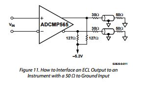
First, in the IC datasheet, they show how to terminate the ECL outputs to drive 50Ω recievers.

enter image description here

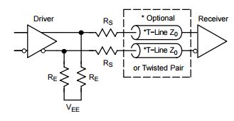
The schematic they show is similar to what is shown in this application note, which is a series termination that assumes unterminated, high-impedance receiver inputs.

enter image description here

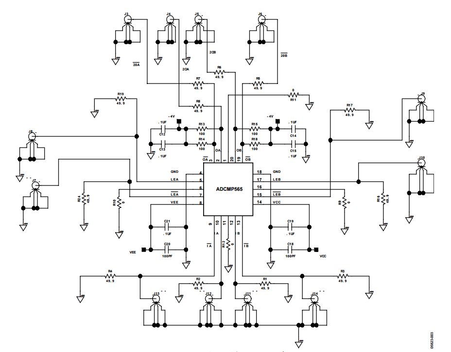
In the evaluation board schematic, you can see the termination at pins 2 and 3 for example, which uses different values for the resistors and the termination voltage in addition to using caps.

enter image description here

My questions are:

  1. Why does the datasheet mention 50Ω receivers while the application note says that this termination is useful for high impedance receivers?
  2. What is the difference between the termination shown in the ADCMP565 datasheet vs that shown in that of the evaluation board?
  3. What are the caps in the eval board termination useful for?

Thank you.

\$\endgroup\$
3
  • \$\begingroup\$ Note: I tried adding pictures of the schematics in the question to make it easier to read, but I couldn't because I'm new to the site. I hope it's clear enough as it stands. If not, then I'd be happy to add them if someone upvotes this so that I have enough reps to do that. \$\endgroup\$ Commented Apr 25, 2016 at 16:34
  • \$\begingroup\$ If you post the image links in a comment, Simone can edit them into your post. \$\endgroup\$
    – uint128_t
    Commented Apr 25, 2016 at 17:20
  • \$\begingroup\$ Sounds good. The 3 figures are here: imgur.com/a/mmu6g The first figure is ther termination suggested by the comparator datasheet. Second one is the termination outlined in the application note. The last one the schematic for the evaluation board. \$\endgroup\$ Commented Apr 25, 2016 at 17:29

1 Answer 1

3
\$\begingroup\$

Why does the datasheet mention 50Ω receivers while the application note says that this termination is useful for high impedance receivers?

This is called series termination.

It prevents ringing when connecting to a high impedance load.

It can also be used with a matched load, but the signal amplitude delivered to the load will be reduced by 1/2. For an eval board, they might assume you are connecting the outputs to an oscilloscope or other measurement device and this attenuation won't affect the system performance.

I don't think the eval board is well designed in that it uses 50 ohms for the series resistor value. The series resistor value should be slightly lower (45 ohms is typical) so that the sum of the driver output impedance and the series resistance is 50 ohms.

What is the difference between the termination shown in the adcmp565 datasheet vs that shown in that of the evaluation board?

Figure 11 in the datasheet shows essentially the same termination, but using 30 ohms for the series resistance. As I mentioned before, it's usual to use a value slightly below 50 ohms to get a better match to the tranmission line.

If you want a really best-effort match, I'd remove the 50 ohm resistors from the eval board (R5, R6, R7, R8) and replace them with 30 ohms, or do some experiments to find an ideal value.

If you're only connecting to 50 ohm loads, it would also be common to replace these resistors with 0 ohms, and rely on the load termination to supress ringing.

What are the caps in the eval board termination useful for?

They're decoupling the -4 V supply so that the output signals don't cause ripple on that supply.

\$\endgroup\$
2
  • \$\begingroup\$ Thank you very much for the answer. So, would you recommend parallel termination over series, if I'm driving 50Ω receivers? \$\endgroup\$ Commented Apr 25, 2016 at 17:26
  • \$\begingroup\$ If you are okay with losing half the signal amplitude, leave it as is (or adjust the series resitors to 30-45 ohms). This will have the least ring. If you need a signal amplitude boost, and you're terminating the far end with 50 ohms, replace the series resistors with 0 ohms. You may also need to be sure you're ac-coupling the rf path to avoid mucking up the dc bias. \$\endgroup\$
    – The Photon
    Commented Apr 25, 2016 at 17:39

Your Answer

By clicking “Post Your Answer”, you agree to our terms of service and acknowledge you have read our privacy policy.

Not the answer you're looking for? Browse other questions tagged or ask your own question.