2
\$\begingroup\$

While evaluating the Libelium Waspmote board for wireless sensor networks, we discovered a strange communication problem.

We tried to set up a link between the waspmote and another board via UART at 115200 Baud using 8N1.

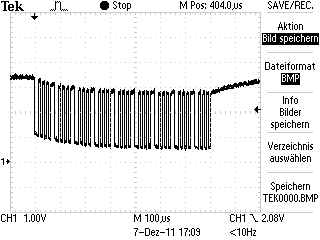
This is the resulting waveform on Tx for sending 9 times 0x55 (01010101b) :
Oscilloscope plot

The levels of high and low degnerate to the treshhold of detection: starting out with a High level of 3.3V, the peaks drop in to about 2.7V and the lows start out at about 1.1V and drop to 0.7V.

According to the target boards specification, the peaks should be > 2.3V and the lows < 1 V for correct operation.

It looks to me as if some capacitve behaviour emerges, but I have no clue why this happens.

I am in need of a clue on what is happening, what i am doing wrong, or what i can do to fix this problem.

Some additional info:

  • The microcontroller on the waspmote is an Atmega1281, and it's uart pins are directly connected to the communication link (no drivers in between).
  • I can not reduce the baudrate since the target board accepts 115200 baud only.

UPDATE 1

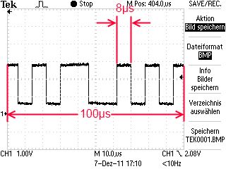
I made a detail shot of the signal. We are looking at a transmission at about 125kHz - which seems to be a bit far off the desired 115200 baud I'm aiming at.
Not quite 115200 baud

UPDATE 2

I measure identical waveforms when I disconnect the traget board and put the oscilloscopes probe directly at the microcontrollers UART-Pin. This seems to rule out problems with the target board. However, the measured baudrate is exactly 125000, which is an error ofabout 8% from the desired target baudrate of 115200. Since the UARTs specification limits the baudrate skew to 2%, I guess there's my problem. However, since the waspmote board is locked to 8Mhz clock rate, the Atmega1281 on the board can not produce a more acurate 115200 baud clock through the prescaler registers ( I checked the manual). I guess I'll need another board to communicate with my target board.

Thanks, everybody.

\$\endgroup\$
6
  • 4
    \$\begingroup\$ That looks almost like the ever present 50/60Hz hum that pervades the universe these days. Check your grounding. \$\endgroup\$
    – Majenko
    Commented Dec 7, 2011 at 9:26
  • \$\begingroup\$ @Majenko - Apearance is sikilar but timing seems to make sense only if he's got 500 Hz mains at 50Hz :-). 100 uS/division = 1 mS across screen and looks like about 1/2 cycle so 2 mS/cycle = 500 Hz. BUT scope may be displaying and image based on multiple cycles \$\endgroup\$
    – Russell McMahon
    Commented Dec 7, 2011 at 10:08
  • \$\begingroup\$ 60hz hum with some 50 mixed in sounds kind of sexy. ;) \$\endgroup\$
    – kenny
    Commented Dec 7, 2011 at 10:09
  • \$\begingroup\$ Are these consistent?. May be : "uart pins are directly connected to the communication link" and The other microcontroller UART is connected to a four channel multiplexer, and it is possible to select ... which of the four new UARTs is required to connect to the UART on the microcontroller. four new UARTs are connected as follows. One is connected to the GPRS board, the other to the GPS and the other two are accessible to the user in the auxiliary I2C – UART connector. Multiplexer configuration is carried out using: { setMuxAux1(); setMuxAux2(); setMuxGPS(); setMuxGPRS() } \$\endgroup\$
    – Russell McMahon
    Commented Dec 7, 2011 at 12:26
  • \$\begingroup\$ It does look like capacitive coupling at first glance, but look closely and you'll see the voltage is actually drifting in the wrong direction. The DC bias should have moved up during the pulses, not down if the signal were capacitively coupled. I'm suspecting this has more to do with power supply droop. I can see these are not the RS-232 levels, but is there possible a charge pump supply in there somewhere? \$\endgroup\$ Commented Dec 7, 2011 at 13:12

2 Answers 2

7
\$\begingroup\$

Your problem is likely in using the wrong baudrate: 112500 is most likely a mistake, the standard rate in that range is 115200 (a search of the manufacturer's website for this number finds many hits, but none for 112500). You could also not be producing the programmed baud rate on one end or the other due to divider granularity; sometimes changing the oversampling of the UART can help. EDIT: Specifically, a value of 8 (divisor of 9) will get you 111111 baud from 8MHz if you set the "double speed" mode bit.

Secondarily, you have a problem such as lack of a common ground between the boards, or haven't grounded the scope to them, thus resulting in the distorted waveform. It's not clear yet if that is what the receiver sees, or if it's merely a measurement mistake in applying the scope.

Additionally, have you verified that the un-named external board also runs without a serial level translator? Most modular inter-board serial communications is at RS232 levels and logically inverted from the logic-level signals, though there are exceptions.

\$\endgroup\$
1
  • 1
    \$\begingroup\$ Actually this was the main problem. The distorted signal is an artifact of a misconfigured osciloscope probe. Accepted. \$\endgroup\$ Commented Dec 19, 2011 at 8:34
3
\$\begingroup\$

As you say - the signal appears to be capacitively coupled - if so it makes relatively good sense of what you see. Unless the scope is capacitively coupled and showing you the effects of that.


A reasonable possibility:

The WaspMote technical guide advises that it has 4 UARTS -
any one of which may be selected by a supplied multiplexer.

Indeed, if you want to see the UART which you are using it MUST be selected by the multiplexer :-) !!!

Section 2.5 page 16 discusses UART and mux pinouts and 2.5.4 on page 18 talks about software mux control.

If you were not correctly selecting the UART it may be capacitively coupling informally. Have you selected the multiplexer correctly?


Some possibility:

Once you are sure of what the DC connection path should be you can check it.

  • Turn off power to all systems. Measure DC continuity end to end on signal line along the longest path that should be DC resistive.

    Is it?

  • Measure ground contunuity from processor ground pin to Waspmote processor ground.

    These should obviously be DC continuous.


Worth a go:

Decide if there is a point in the TX cct as close to the signal origination point that may be grounded or pulled down with a small value resistor. Also maybe pulled to supply. If so, do so and see if the DC level remains and does not just cause a capacitively coupled excursion.


Getting desperate

Is a driver unpowered so that the signal excursion powers it but the supply then starts to decay under load.

\$\endgroup\$
1
  • \$\begingroup\$ Look at the polarity of the drift and you can see it is not due to capacitive coupling. If so, the drift would have been upwards during the pulses, not down as shown. \$\endgroup\$ Commented Dec 8, 2011 at 13:17

Your Answer

By clicking “Post Your Answer”, you agree to our terms of service and acknowledge you have read our privacy policy.

Not the answer you're looking for? Browse other questions tagged or ask your own question.