1
\$\begingroup\$

Referring to the below output matching network of an amplifier ,in which gamma_out is chosen as the complex conjugate of gamma_l (in the figure Γ and Γ*) in order to achieve maximum power transfer from the output of the amplifier to the network. Why in this particular case of conjugate matching Γ1 turns out to be 0 ? Can somebody carefully explains me this perhaps trivial thing? thank you in advance.
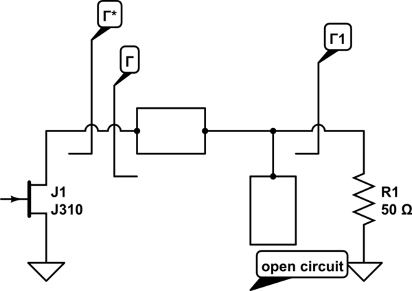
schematic

simulate this circuit – Schematic created using CircuitLab

\$\endgroup\$
3
  • \$\begingroup\$ Now I only did one class on microwave theory at uni, but wouldn't a gamma 1 of zero mean that no power is being reflected back from to load towards the generator? In other words, zero insertion loss or a perfect impedance match or have I missed something? \$\endgroup\$
    – Sam
    Commented May 14, 2016 at 23:11
  • \$\begingroup\$ Yes it means that, but my problem here is another: normally the gamma that you see at the output of the transistor is equivalent to an impedance, and after you have to transform that impedance through all the matching network in order to find what impedance you see at Z1 or equivalently what reflection coefficient you see in gamma1. And the thing is that in my opinion that gamma1 is not 0 in general, but from the textbook it seems to be always 0 for this case of conjugate matching. \$\endgroup\$
    – Simon
    Commented May 14, 2016 at 23:16
  • \$\begingroup\$ doesn't gamma = (Z1-Z0)/(Z1+Z0) so if Z1=Z0 (i.e. a perfect match) gamma would always be zero, even if the impedance of the transistor is different to the load the matching network transforms the impedances so the transistor has a conjugate match and the load has a conjugate match (this will only work at a certain frequency though). If you were looking at the point between the two transmission lines, gamma would most certainly not be zero. Conjugate matching (or matching in general) means a gamma of zero, without the network gamma would have some non-zero value though. \$\endgroup\$
    – Sam
    Commented May 14, 2016 at 23:41

1 Answer 1

1
\$\begingroup\$

Since the load exactly 50 ohms, it will have a gamma of zero. You want the gamma looking back into your matching circuit (gamma 1) to also be exactly zero.

\$\endgroup\$
1
  • \$\begingroup\$ I understand the gamma looking into the load is 0, but why you say that also the gamma1 (looking in the opposite direction) needs to be 0? In my understanding gamma1 is gamma* putted backwards to the matching network until the point in witch we see gamma1. \$\endgroup\$
    – Simon
    Commented May 15, 2016 at 8:23

Your Answer

By clicking “Post Your Answer”, you agree to our terms of service and acknowledge you have read our privacy policy.

Not the answer you're looking for? Browse other questions tagged or ask your own question.