23
\$\begingroup\$

I have many PCBs that use an AVR in SMD packaging, and since I frequently change the firmware in prototype boards, I'm trying to come with the best solution to program the AVR quickly and easily.

The first approach was to have a standard header (2x5 pins, .1") on the board, but since these are bulky (for the size of the boards I'm dealing with), I started to have just the contact holes without soldering the header, and bent the pins of a header with a plier so I could "snap" it in and out the board. Not an optimal solution, but it worked.

The next step was to use gold fingers (i.e. one edge of the board would have some contacts exposed, like those old ISA boards, but with just a few contacts of course). The problem with it is that the board cost increases, and still uses a lot of "real estate".

Any suggestion for small+cheap+clean alternatives? Ideally, without having to solder anything on the board (like with the gold fingers). I was thinking about just some small contacts on the board and maybe two aligning holes, if there's a connector that could fit there and by some way stay in place while the programming is done.

BTW, although the standard connector has 10 pins, only 6 are required.

\$\endgroup\$
1
  • \$\begingroup\$ I suggest you make the title more general. This question isn't specific to Atmel microcontrollers. How about this: "Suggestions for small and handy connector for in-circuit programming?". \$\endgroup\$ Commented Dec 14, 2011 at 22:36

8 Answers 8

13
\$\begingroup\$

Take a look at www.tag-connect.com. They supply programming cables that mate to a small board pad layout. Include the layout on your board and your all set.

\$\endgroup\$
1
  • \$\begingroup\$ That's exactly what I was looking for, many thanks! \$\endgroup\$
    – fceconel
    Commented Apr 26, 2013 at 20:57
15
\$\begingroup\$

Go with a set of test pads, if you're going for a production run.

You can easily get at them with pogo pins - you stick them into a breadboard at predefined locations, and just press your board against it. I've been using this approach for Microchip's ICSP quite well - it also allows you to put the contact pads almost anywhere on the PCB - which simplifies routability for dense circuits.

Adafruit has a nice pack, but they can be purchased from a warehouse distributor like Digikey(US) or Farnell(EU) as well.

http://www.adafruit.com/products/394


Added: My favourite way to use pogo pins:

Take 3 PCBs of your target device.

PCB #1 is your target PCB - it will be programmed, and you should populate it fully.

PCB #2 is the guide PCB - drill holes (large enough for pogo pins' head) through all the test pads - it's easier since you see the location. If necessary (such as no mounting holes to begin with), drill holes for spacers too - you're sacrificing this PCB, if you are concerned with the cost at small volume, copy the design over to a blank plastic board, and use it instead.

PCB #3 is the connected PCB - again, drill holes through all the test pads, this time large enough to fit the tail of the pogo pin. Drill holes for spacers - this is also a sacrificial PCB.

Solder the pogo pins to PCB#3, at such depth that the heads stick out 5mm above PCB#2, with the spacers you have. Solder all the required cables.

Apply eletrical tape or insulating lacquer on PCB2.

Screw the spacers in, screw the PCB#2 above. This should look like there are just heads of pogo pins sticking out.

Press the target PCB#1 aligning it with PCB#2.

Profit :)

\$\endgroup\$
4
  • \$\begingroup\$ Do you know of what material they're made? I'm asking because it wouldn't be practical to use spacers, but if magnetic I could hold them in place with a magnet at the other side of the board. \$\endgroup\$
    – fceconel
    Commented Dec 14, 2011 at 19:01
  • \$\begingroup\$ Don't bother with spacers, in most cases the pogo pins have enough give to deal with PCB at a slight angle. What matters is whether you can get the PCB in the right alignment with the pins. \$\endgroup\$
    – qdot
    Commented Dec 14, 2011 at 19:04
  • 1
    \$\begingroup\$ Added a section on how I use pogo pins in small-volume (10+) programming. \$\endgroup\$
    – qdot
    Commented Dec 14, 2011 at 19:12
  • 1
    \$\begingroup\$ @qdot - Your method is a lot like Sparkfun's pogo pin production lines, which has some nice illustrations for the method. I personally don't like it; but I get to send my pogo pin needs off to a CNC machine that drills holes at the right spots in a piece of phenolic which has been cut to the right shape for my testing machine :) \$\endgroup\$ Commented Jan 23, 2012 at 0:41
7
\$\begingroup\$

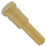
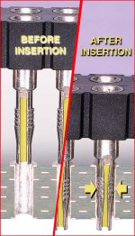
The answer given by @qdot is a good one. I just thought I'd mention that I've seen someone implement an alternative design for a programming header. He used fat pogo pins that seemed to have a slight taper to them. The board under test had large plated through-holes/vias that made a conforming contact with the pogo pins to make the electrical connection. That is, a pogo pin could be inserted into the plated hole and it would provide a sufficient but not over tight fit. Several pogo pins were soldered into a PCB such that that they would align with the vias on the test board and connect with it. In this way he made his own pogo pin connector to mate with the test board. I beleive he made this work with plated through holes where you would put a standard 0.1" pitch ISCP header. Instead of soldering in the header, he just mated his pogo-pin connector with it and could program the micro through it. It seemed really convenient to me. I tried to find a picture of this but it seems to be a relatively unique approach to this problem. The pins looked something like in this picture, but, they had a taper on the springy pin part that made it so they made a tight fit with the through hole on the test PCB:

similar spring pin

http://search.digikey.com/ca/en/products/0906-4-15-20-75-14-11-0/ED8184-ND/1147052

This is as close as I can find a picture illustrating this idea:

similar system

https://www.mill-max.com/new_products/detail/22

I thought this was interesting because in this arrangement the pogo pins held the test board in place in addition to providing the electrical connection. If you use pogo pins that press against pads, you also have to find a way to constrain the board so that the only degree of freedom is in the pogo pin actuation direction and you must provide continuously light pressure. That is you have to make a test fixture. With the method I suggest you don't have to make a test fixture.

\$\endgroup\$
4
  • 1
    \$\begingroup\$ In a pinch, you could jam the pogo pins directly into female receptacle (like the one on the PicKit), and use this 5-pogo contraption as a compression connector. \$\endgroup\$
    – qdot
    Commented Dec 14, 2011 at 19:53
  • 1
    \$\begingroup\$ samtec.com/ProductInformation/TechnicalSpecifications/… \$\endgroup\$
    – B Pete
    Commented Dec 15, 2011 at 0:06
  • \$\begingroup\$ I recently used parts from the series I linked in the comment above for programming in a low volume production enviornment. The pogo assemblies do need to be reflow soldered to the programming jig board though, whcih may present problems for some. \$\endgroup\$
    – B Pete
    Commented Dec 15, 2011 at 0:15
  • \$\begingroup\$ Seems promising... depending on the required hole size may be a better solution than the pogo pins, since there's no need for additional parts to hold it in place. I'll buy some and give a try. \$\endgroup\$
    – fceconel
    Commented Dec 15, 2011 at 23:23
5
\$\begingroup\$

While looking for a solution to the same problem, I came across the Pogo-Key, an open source board for creating a pogo-pin based programming key. Similar to the Tag Connect ones mentioned earlier, that you can build yourself, but without the registration pins or legs that clip it in to your board.

\$\endgroup\$
4
  • \$\begingroup\$ That's a good cheap alternative, indeed. But the main problem there is not to have a way to lock the connector in place, that's the main reason I accepted the tag-connect answer as the best one. I've tried to make a connector myself with pogo pins but abandoned the idea due to that. \$\endgroup\$
    – fceconel
    Commented Dec 2, 2013 at 23:00
  • \$\begingroup\$ That is a nice feature though it does waste some board space on the holes the clips go through. It looks like the pogo key was designed for really limited board space, on a button sized board. \$\endgroup\$ Commented Dec 3, 2013 at 2:26
  • \$\begingroup\$ Indeed, the ideal would be to have some way to lock it using a tool external to the board. I once thought of designing a 3D model somewhat like a clothespin that the pogo connector would be attached to, and order it at Shapeways, but was discouraged to finish when I knew there was a ready-made product. \$\endgroup\$
    – fceconel
    Commented Dec 3, 2013 at 14:54
  • \$\begingroup\$ (might belong as a separate answer) but anyone looking for this type of solution with a clip, dfrobot has the eClip (documentation here). the design allows you to attach the included pinouts+pogos for some standard sizes, or design your own PCB to match your hardware, and switch between different pin layouts. the template files are located on the github. the design is pretty solid, and with larger pogo pins mentioned here, may work with empty plated holes \$\endgroup\$
    – aquafunk
    Commented Sep 3, 2016 at 19:21
4
\$\begingroup\$

I build a small adapter PCB using the Staggered SOLO Stacker from AVX for programming AVRs. See http://daniel-spilker.com/blog/2011/04/25/isptouch-for-avr-microcontrollers/ for details. I also created an Eagle library since the adapter requires a custom footprint.

\$\endgroup\$
3
\$\begingroup\$

For tight boards, I use a set of pads sized for a 1.27mm pitch pin-header strip, with holes just big enough for the pins. For handheld connection, use fairly long pins (8-10mm), and you just insert the pins, and hold them with pressure applied parallel to the PCB, so the springiness of each pin provides a good contact against the sides of the plated holes.

\$\endgroup\$
0
1
\$\begingroup\$

Go with fingers without the gold plating. Why do you need the high reliability of gold fingers when the board connector will be handled in real time? Use a board edge connector to make the contact.

\$\endgroup\$
1
  • \$\begingroup\$ Thanks, I agree that it should reduce the cost, but that's not the only concern. The fab I use charges extra when there are contacts at the edges, and also there's the problem of the space the fingers use. \$\endgroup\$
    – fceconel
    Commented Dec 14, 2011 at 19:06
1
\$\begingroup\$

You do not actually need 6 pins for ISP, especially if you can re-use the board's power connections.

In addition to the ground reference, you need reset, clock, and two directions of data, for a total of 4 or 5.

At that point, you can use a single row header, un-soldered, and hold the header pins at an angle to the board to insure contact.

The advantage of this over pogo pins is that header pins are more durable, cheaper to replace (use a socket on your cable and a replaceable loose strip of pins in between), and available in higher pitch density.

Pogo pins do make sense when you have a lot of connections to pick up, need to clamp the connection for operations lasting beyond a few seconds, or when they are scattered around the board rather than in a conveniently short row. But they require you to design something of a fixture.

\$\endgroup\$
6
  • \$\begingroup\$ The 6 pins are because the board is not powered otherwise when programmed (I hooked the power to the AVR programmer, so that I could simply connect, program and disconnect). \$\endgroup\$
    – fceconel
    Commented Dec 14, 2011 at 19:34
  • 1
    \$\begingroup\$ Got it. There's always the option of using aligator clips or grabbers or the intended power harness to power it. A lot depends on how many of them are going to be done by how careful a technician - volume (or a double-in-line requirement) points to investing in carefully engineered jigs with pogos, prototype scale points to simple, pragmatic, maintainable things like the single inline header held at an angle. \$\endgroup\$ Commented Dec 14, 2011 at 19:39
  • 1
    \$\begingroup\$ OK, but there's a catch: if you lose connection to one of the pins during programming, you risk putting the AVR in an unrecoverable state (I did that twice). So the pogo pins become more important to make sure that won't happen. \$\endgroup\$
    – fceconel
    Commented Dec 14, 2011 at 22:22
  • \$\begingroup\$ @fceconel - good point, the holding at an angle is a technique I've used with CPLDs rather than AVRs (for which I've so far been able to include actual connectors) \$\endgroup\$ Commented Dec 14, 2011 at 23:36
  • \$\begingroup\$ @fceconel - "Unrecoverable"? You've got a programmer in your hands! It's not like you're relying on a bootloader. I suppose it's possible that you've lost the power connections, and are powering the AVR through the protection diodes on the IO pins (which could damage it), but corruption of the data shouldn't be a problem. \$\endgroup\$ Commented Jan 23, 2012 at 0:45

Your Answer

By clicking “Post Your Answer”, you agree to our terms of service and acknowledge you have read our privacy policy.

Not the answer you're looking for? Browse other questions tagged or ask your own question.