8
votes
\$\begingroup\$

I have a LED Christmas lights string, which consists of two circuits of LEDs connected serially. It is working directly on 110V AC. Most LED sockets have 2 wires connected to them, some have three. There is a 110V socket on the other end of the string, so these can be chained together.

One half of the string went dark, so I suppose one of the LEDs on that circuit is bad, or its connection is faulty.

LEDs are non-removable (molded plastic socket with lens), and I hope I can trace the string somehow and find where the fault is. Obviously cutting insulation in 50 places in order to test each LED separately is not an option...

If there any sane way to find the fault, either by buying some equipment or building DIY one, or do I need to just replace 100 LEDs string because one went bad?

\$\endgroup\$
4
  • \$\begingroup\$ how seasonally appropriate... :) \$\endgroup\$
    – vicatcu
    Commented Dec 16, 2011 at 19:37
  • 6
    \$\begingroup\$ Don't cut the string in 50 places! Binary chop your way through and solve the problem in O(log N) time en.wikipedia.org/wiki/Binary_search_algorithm First divide into {50} -> {25,25} -> {{12, 13},{12,13}}, -> etc. \$\endgroup\$ Commented Dec 16, 2011 at 20:47
  • 1
    \$\begingroup\$ Check out this video: youtube.com/… Uses a small circuit and a buzzer to detect where the ac noise stops. \$\endgroup\$
    – captncraig
    Commented Dec 16, 2011 at 22:36
  • \$\begingroup\$ Your answer is here: Coming this year (2012) vimeo.com/37397543 ledkeeper.com \$\endgroup\$
    – user9049
    Commented Apr 3, 2012 at 23:14

4 Answers 4

9
votes
\$\begingroup\$

I just saw a great and simple project that does just this:

http://www.youtube.com/watch?list=PLFA57ACAC0F0DE0D1&feature=player_detailpage&v=cwiLQWJq2LQ

enter image description here

The project is by Alan Yates: http://www.vk2zay.net/

As I understand it, it uses a high impedance gate of a JFET to detect fluctuations in the E-field in the wires due to noise on the mains. The signal is amplified using a BJT to make sound on a piezoelectric speaker. If a light is burned out it the E-field will exist on the wire going into the light, but, not on its exit wire. Using this principal it is easy to locate the burned light. He applies this to incandescent light string, but, the same principal would apply to an LED string.

\$\endgroup\$
4
  • \$\begingroup\$ Thanks for the screenshot and the explanation. Will try building something like this. In all fairness, though, @CMP posted this video link as a comment above earlier... \$\endgroup\$
    – haimg
    Commented Dec 19, 2011 at 17:14
  • 1
    \$\begingroup\$ @haimg: Real fairness would be to give Alan Yates all the credit; I certainly tried to do this. I didn't see CMP's comment, but, I did go the distance to make this understandable without leaving the stack-exchange, which was his option too. I personally think that deserves the win, which apparently you agree with. So thanks! I highly recommend that everyone check out Alan's site. This guy really knows his way around the analog and RF. \$\endgroup\$ Commented Dec 19, 2011 at 18:22
  • \$\begingroup\$ wow, this is way simpler than what I suggested... brilliant! \$\endgroup\$
    – vicatcu
    Commented Dec 20, 2011 at 16:19
  • \$\begingroup\$ maybe see also sentex.ca/~mec1995/circ/xmasbulb.html \$\endgroup\$
    – cwd
    Commented Dec 8, 2014 at 0:22
2
votes
\$\begingroup\$

How about using two needles (or pins) to "short" one led at the time by pressing through the plastic insulation?. Just saw that this is directly connected to the mains, so better use a transformer, plastic covered needles and an insulation mat

\$\endgroup\$
2
votes
\$\begingroup\$

The JFET sniffer is great, but if you happen to be at your local electronics store with a single 399 dollar bill and there are no FETs available, you could buy an oscilloscope to do the mains sniffing.

All you have to do is to plug in the xmas light chain in such a way that the live conductor is the one that gets interrupted by the bulb sockets. In this way, by simply touching the insulation of the wire entering and exiting each bulb socket with the tip of the probe, you can see the ghost of the mains' live. Until you reach the first faulty bulb, that is.

This is the 'background E-field' sensed as a voltage by the probe's tip, when the probe is nowhere near the powered xmas lights (5 - 10 inches away are enough to avoid detection).
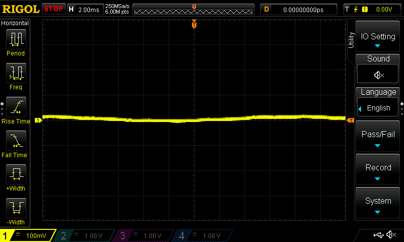
Background E-Field

And this is the 'field' sensed on the live wire, before any bulbs (and with the light chain dark because of one dead bulb).
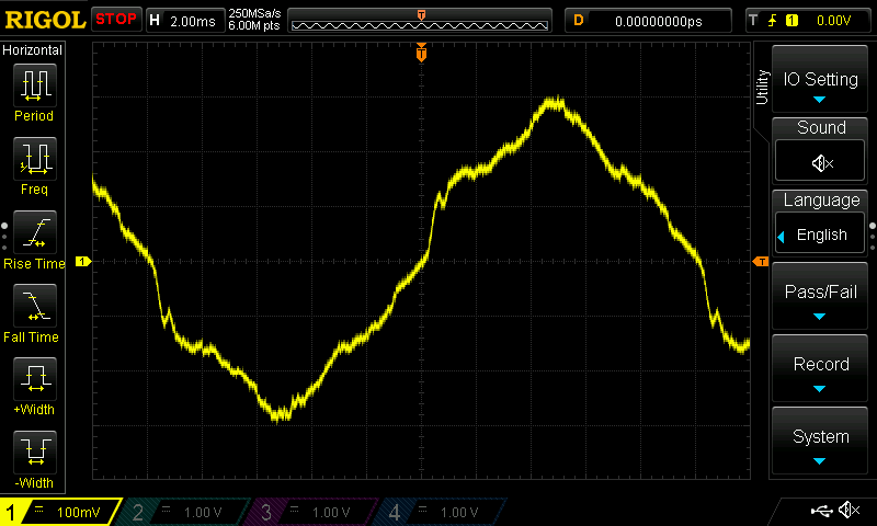
Mains Field near the plug

The probe was stripped of the ground clip and the retractable tip; you only need to touch the insulation with the tip. The oscilloscope's scales were set to 100 mV/div vertical and 2 ms/div horizontal. (With another, much older, set of lights with very thin wires I had to use 500 mV/div to avoid clipping and see the full sine wave).

Now, when you reach the first dead bulb you will see the ghost of the mains on one end and almost nothing on the other:
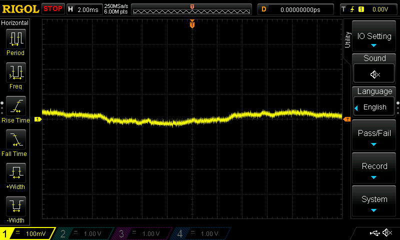
E-field after a dead bulb

(Sorry about the following pictures, I used my cellphone and I cut out the most important part, i.e. the bulb).
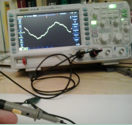
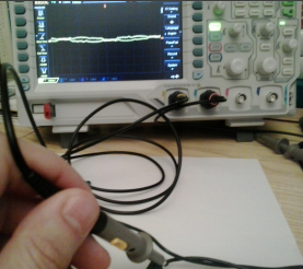
Before a dead bulb after a dead bulb

You can approach the dead bulb by binary search, if you wish to go full scientific. When you have replaced the first dead bulb found, repeat until you find all dead ones (they will be on the remaining portion of the string away from the plug).

Once the chain is repaired, well, it will light up. But if your eyes are glued to the scope screen and you don't have a solvent at hand, you could still tell because you will be able to see the ghost of the mains sine on both ends of all bulbs.
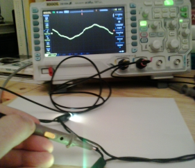
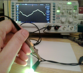
before a good bulb after a good bulb

Now, try to picture yourself on a ladder, with the scope held by a strap around your neck, trying to reach the lights at the top of the tree. Isn't it the most wonderful time of the year?


\$\endgroup\$
1
vote
\$\begingroup\$

I've contemplated this myself a number of times... but honestly I've never gone through with it because it's so cheap (albeit environmentally irresponsible) to just go out and buy a new strand.

At any rate, one way I could envision doing it, were I to design a DIY method, would be to transmit a very narrow pulse signal down the "neutral" input, and measure the time it takes to get a reflection of the pulse at the source.

I would generate the pulse with a general purpose I/O pin of a microcontroller which I would subsequently configure as a tri-stated input. I would "listen" for the pulse with an A/D input pin on the microcontroller. This could probably even be the same pin of the microcontroller. You might also want to put a current limiting resistor between the microcontroller pin and the strand of lights.

Knowing how long the pulse took to be reflected, it should be a relatively simple calculation to figure out how far down the strand the broken circuit is. I think it would actually just be (to a close approximation):

$$length = \frac{speed\;of\;light \times measured\;duration}{2}$$

Now, this will probably only work if half your lights are functioning and the other half aren't. If all your lights are out, I would expect you'd get two (possibly) overlapping reflections, which would make the measurement kind of ambiguous. Interpreting the measurement would also require some knowledge of the circuit topology of your particular strand as well I would imagine, but it would at least give you something to go on.


Edit / Additions

The main problem here is being able to sample quickly enough. At the speed of light, 6 inches takes about half a nano-second by my calculations, so you need a timer running at almost 4GHz to sample quickly enough to narrow it down to 6 inches of length. This pretty much kills the idea of an A/D converter being your trigger, and you'd need some kind of high bandwidth Analog comparator set up with a low trip point to "amplify" the pulse and cause a pin change interrupt that you could use to capture a free running timer.

Lets say you're using an Arduino running at 16MHz. Your timer resolution is then is theoretically 62.5ns. That means you have a length resolution of 18.7 meters, ouch. OK, so we need a faster clock. If you had an FPGA running at 1 GHz, you could get it down to about 0.3 meters or just under a foot. But now we're starting to kind of push the limits of DIY-ability.

\$\endgroup\$
5
  • \$\begingroup\$ Think about it. This is well beyond ordinary microcontrollers. At about a foot per nanosecond, you would need much higher resolution than a ordinary micro. Even something like a dsPIC running at 40 MIPS has a 25ns instruction cycle time. That's a lot of propagation distance. Maybe you could set up a fast pulse generator with a fast scope, but I expect you won't get one nicel clear and obvious reflection anyway. \$\endgroup\$ Commented Dec 16, 2011 at 20:08
  • \$\begingroup\$ @OlinLathrop I must have been adding my additions while you wrote this comment, so you see I did think about it, just submitted my thoughts iteratively. \$\endgroup\$
    – vicatcu
    Commented Dec 16, 2011 at 20:15
  • 1
    \$\begingroup\$ That is why instead of using an ADC, you use some 7414s in parallel to give a good solid square wave with sharp edges and watch the line with an oscilloscope. calculate the distance by looking at the trace on the scope. Same idea, but without trying to do it in software. :-) \$\endgroup\$
    – akohlsmith
    Commented Dec 17, 2011 at 16:02
  • \$\begingroup\$ @AndrewKohlsmith Right on! The only drawback is that a personal oscilloscope is pricey. This would have been a great application for that 7400 series logic contest earlier this year. Is there a really high speed 16-bit or 32-bit counter IC that could be used for capture in place of the scope? \$\endgroup\$
    – vicatcu
    Commented Dec 20, 2011 at 16:17
  • \$\begingroup\$ Eh... you can get usb logic analyzers for under $10. Just have to induce a pulse and know how to read the echo... \$\endgroup\$
    – user61387
    Commented Dec 14, 2014 at 4:54

Not the answer you're looking for? Browse other questions tagged or ask your own question.