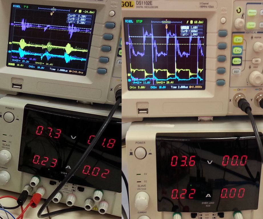
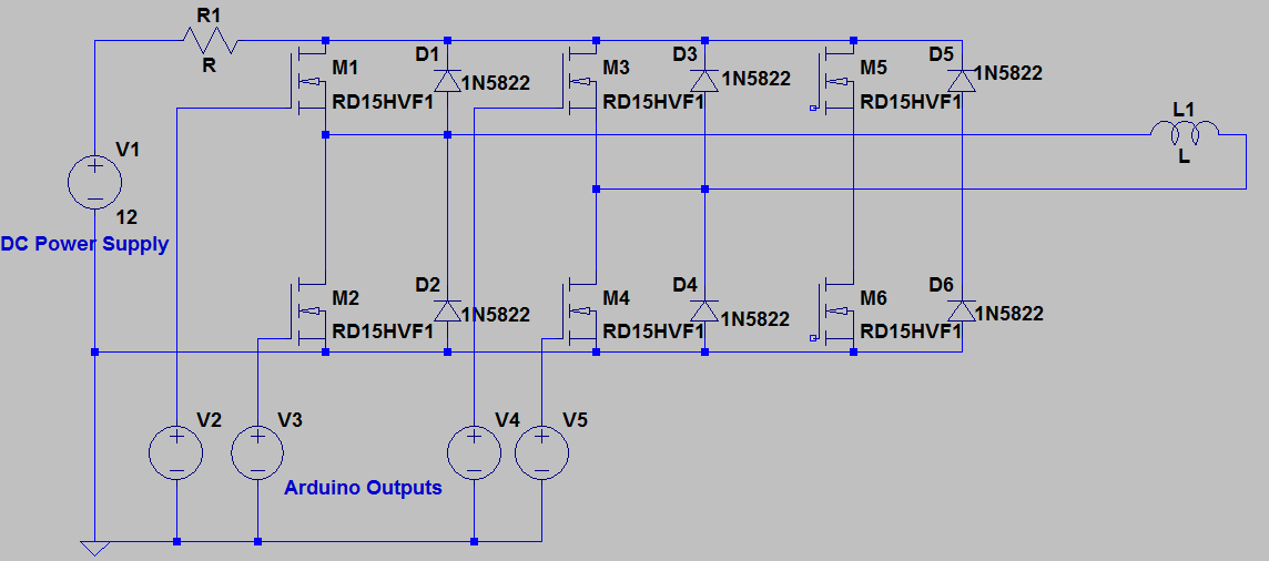
I am working on a wireless charging project that needs a three-phase inverter. I built the inverter (with flexible wiring using connectors) myself and tested it as a single-phase full bridge converter at first. The inverter worked fine for resistive load (although there were so many noises in the waveform), but when the coil was connected, the voltage across the coil was totally distorted (not a square wave and I don't know what is that). I would like to ask what could be the possible reason(s) for this?
 Inverter test for coil (left) and for resistive load (right)
 This is the circuit of the inverter test for coil. For resistive test, the circuit was just similar to this one but with R1 being removed and L1 being replaced by resistor.
-Coil inductance = 3.9uH
-Switching frequency = 128kHz
At the moment of switching, there was no secondary coil. The coil connected to the inverter just acted like an inductor. Thank you!
