39
\$\begingroup\$

I think I understand more or less how an ordinary semiconductor diode works: Crystal doped differently in different regions, carrier depletion where they meet, bla bla bla.

However, actual diodes that one builds circuits with do not end with bits of n-doped and p-doped silicon. They're little ceramic/plastic packages with metal leads coming out of the ends. Somehow the current needs to pass between those metal leads and the semiconductor inside.

And there's a problem. If I understand things correctly, a metal ought to be the ultimate n-carrier material -- every atom in the lattice contributes at least one electron to a conduction band. When we stick a metal lead onto the p-doped end of the semiconductor, we ought to get another pn-junction, one that goes in the wrong direction for forward current to flow.

How come the entire component can conduct in the forward direction anyway?

Is it just a matter of making the area of the silicon-metal interface so big that the total reverse leakage current of the p/metal junction is greater than the forward current we want the entire diode to carry? (I'm imagining large volumes of finely interdigitated metal and silicon for multi-ampere rectifiers). Or is there something else going on?

\$\endgroup\$
2
  • \$\begingroup\$ I believe your confusion is due to you treating "holes" the same as electrons. You must keep in mind that at any time, the only things that move, are the electrons! When an electron moves, it fills a "hole" and also creates a "hole." The best example is the Chinese checkers game. The marbles are the electrons and the holes on the board are the "holes" in the semiconductor. As a marble moves into a hole, the hole "moves" to where the electron was. You also seem to miss the point that the metal to semi junctions, are essentially "ohmic" junctions, NOT semiconductor junctions! \$\endgroup\$
    – Guill
    Commented Jul 21, 2016 at 6:21
  • \$\begingroup\$ @Guill: The Chinese checkers metaphor for holes is good for schoolchildren and housewives. In solid-state physics there is no checkers, there is no spatial “holes” and motion of quantum particles is understood as their momentum, not departure from the point A and arrival to B. \$\endgroup\$ Commented Aug 24, 2016 at 17:56

2 Answers 2

32
\$\begingroup\$

There is a type of diode called a Schottky diode, which is basically a metal-semiconductor junction, so it raises the question, how do you form a metal contact with any semiconductor device, not just a diode.

The answer lies in why a metal-semi junction exhibits diode behaviour in some circumstances. First we need to look quickly at the difference between metal and n-type and p-type semiconductors.
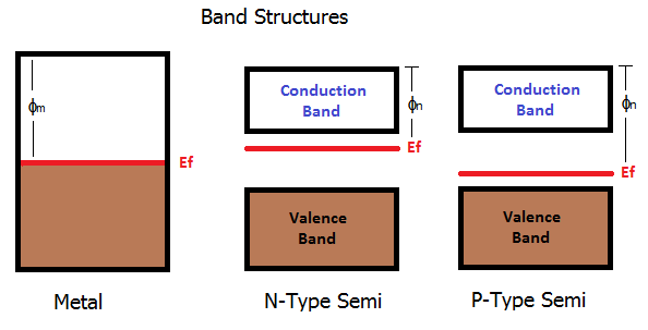
Metal and Semiconductor Band Structures

Metals are a continuous band of electron states. Electrons prefer to be in the lower states, so this is show with the shaded brown region. The red line indicates the average energy level (Fermi level) which in the metal is basically how "full" it is with electrons. There is then an escape energy where electrons are no longer bound to the structure - they become free. This is shown as the work function \$\phi_m\$.

For semiconductors, the bands are a little different. There is a gap in the middle where electrons don't like to be. The structure is split into the valence band which is typically full of electrons, and the conduction band which is typically empty. Depending on how much the semiconductor gets doped, the average energy will change. In n-type, additional electrons are added to the conduction band which moves the average energy up. In p-type electrons are removed from the valence band, moving the average energy down.

When you have a discrete junction between the metal and semiconductor regions, in simplistic terms it causes bending of the band structure. The energy bands in the semiconductor curve to match those of the metal at the junction. The rules are simply that the Fermi energies must match across the structure, and that the escape energy level must match at the junction. Depending on how the bands bend will determine whether and an inbuilt energy barrier forms (a diode).


Ohmic Contact using Work Function
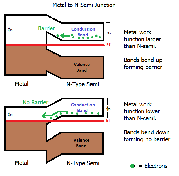
N-type Metal Junction

If the metal has a higher work function than an n-type semiconductor, the bands of the semiconductor bend upwards to meet it. This causes the lower edge of the conduction band to rise up causing a potential barrier (diode) which must be overcome in order for electrons to flow from the conduction band of the semiconductor into the metal.

Conversely if the metal has a lower work function than the n-type semiconductor, the bands of the semiconductor bend down to meet it. This results in no barrier because electrons don't need to gain energy to get into the metal.
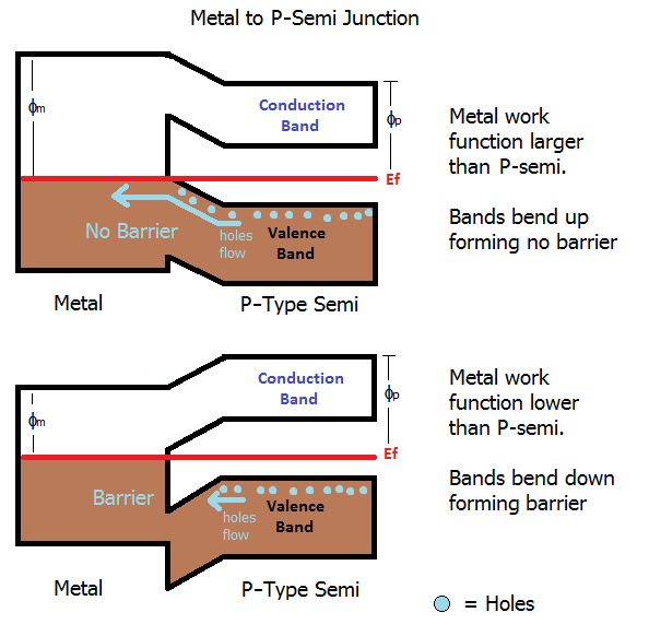
P-Type Metal Junction

For a p-type semiconductor, the opposite is true. The metal must have a higher work function that the semiconductor because in a p-type material the majority carriers are holes in the valence band, so electrons need to flow from the metal out into the semiconductor.

However, this type of contact is rarely used. As you point out in the comments, the optimal current flow is the opposite from what we need in the diode. I chose to include it for completeness, and to look at the difference between the structure of a pure Ohmic contact and a Schottky diode contact.


Ohmic contact using Tunnelling
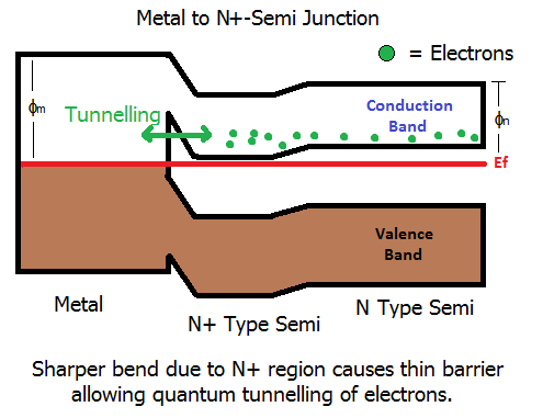
Tunnelling in N+ Metal Junction

The more common method is to use the Schottky format (which forms a barrier), but to make the barrier larger - sounds odd, but its true. When you make the barrier larger, it gets thinner. When the barrier is thin enough, quantum effects take over. The electrons can basically tunnel through the barrier and junction loses its diode behaviour. As a result, we now form an Ohmic contact.

Once electrons are able to tunnel in large numbers, the barrier basically becomes nothing more than a resistive path. Electrons can tunnel both ways through the barrier, i.e., from metal to semi, or from semi to metal.

The barrier is made higher by more heavily doping the semiconductor in the region around the contact which forces the bend in the bands to be larger because the difference in Fermi level between the metal and semiconductor gets larger. This in turn results in a narrowing of the barrier.
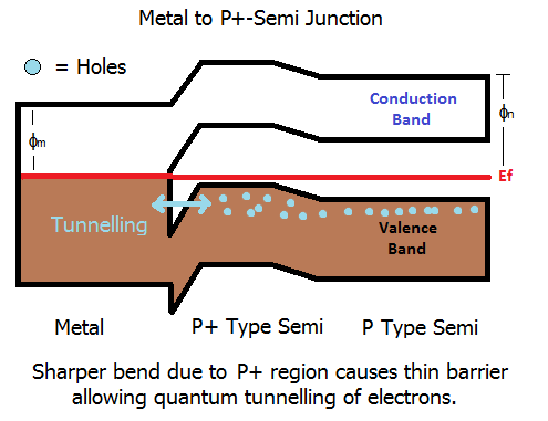
Tunnelling in P+ Metal Junction

The same can be done with a P-type. The tunnelling occurs through the barrier in the valence band.


Once you have an Ohmic connection with the semiconductor, you can simply deposit a metal bond pad onto the connection point, and then wire bond those to the diodes metal pads (SMD) or legs (through-hole).

\$\endgroup\$
13
  • \$\begingroup\$ I may be confused here, but don't you have the direction of the electron flow reversed? In the forward direction, current flows across the main junction from the p-type region to the n-type region (the electric field pushes both kinds of carriers into the junction, where they can annihilate), which means that electrons should flow in the other direction: from the p-type silicon into its attached metal lead. \$\endgroup\$ Commented Jul 9, 2016 at 18:17
  • \$\begingroup\$ @HenningMakholm in a diode, yes, the electrons will flow from N-Type to P-type. Now that I have added the diagrams, things should be a little more clear. If the electrons are flowing from N to P, it must be flowing from the metal in to the N-type semiconductor, and from the P-type in to the metal. This is possible using the barrier tunnelling method as current can go both ways through the barrier. \$\endgroup\$ Commented Jul 9, 2016 at 18:39
  • \$\begingroup\$ x @Tom, no I'm still confused. You write "in a p-type material the majority carriers are holes in the valence band, so electrons need to flow from the metal out into the semiconductor" -- but in a forward-biased diode, the end with p-type material is the one where we want electrons to flow into the metal lead and away towards the rest of the circuit. \$\endgroup\$ Commented Jul 9, 2016 at 18:44
  • \$\begingroup\$ @HenningMakholm I've tried to clarify the answer a bit more. The pure Ohmic contact is rarely used for the reasons you highlight - in the case of the diode, we need the current to flow the other way. But I wanted to include it for completeness. In the case of a solar cell (a type of diode), the current flows the other way, so the first sort of contact is applicable. \$\endgroup\$ Commented Jul 9, 2016 at 18:59
  • \$\begingroup\$ Hmm, so the last of your diagrams, "Metal to P+ Semi Junction" is the situation I'm interested in. And if I understand things correctly now, the point there is that just a slight lowering of the potential in the silicon will raise the energy levels of all electrons there, such that the upper part of the valence band ends up above the red lines. Then some of the valence-band electrons in the P+ can tunnel to the unoccupied states in the metal, leaving holes that can then be sucked off towards the right. Is that about right? \$\endgroup\$ Commented Jul 9, 2016 at 22:00
12
\$\begingroup\$

The contact you're referring to is known as an ohmic contact in the industry, and is an important and often difficult facet of semiconductor processing metallurgy. Some would say more an art than a science, at least in practice.

You're right that a simple metal-semiconductor contact forms a P-N junction, generally known as a Schottky junction, and that is undesirable at a semiconductor to conductor interface.

To get around the inherent Schottky nature of semi-to-metal junctions, firstly usually the semiconductor is heavily doped at the intended contact, to keep the depletion region very small. This means that electron tunnelling, rather than "normal" junction physics is the important electron transportation mechanism in an ohmic contact.

Secondly, specific contact metals, called transition metals, are deposited and alloyed at elevated temperatures into the silicon at the contact area, which further act to form a good ohmic contact with the bond wires that ultimately are bonded to the contact. The transition metals are highly dependant on the type of semiconductor, but aluminum, titanium-tungsten, and silicides are commonly used for silicon semiconductors.

\$\endgroup\$
2
  • \$\begingroup\$ I'm trying to see how electron tunneling would help at the anode end, but failing. We need a steady stream of electrons flowing away into the metal, but in the p-type semiconductor there are no free electrons that could tunnel anywhere. If a valence electron in the p-type semiconductor decides to tunnel into the metal, isn't that just the thermal pair production that is usually responsible for the reverse current? I thought that was a part of "normal junction physics". \$\endgroup\$ Commented Jul 9, 2016 at 18:29
  • \$\begingroup\$ @Henning Makholm: It’s not crucial whether an electron departs the semiconductor from the conduction band (virtually empty in the p type) or from the (upper) valence band. \$\endgroup\$ Commented Aug 24, 2016 at 18:08

Your Answer

By clicking “Post Your Answer”, you agree to our terms of service and acknowledge you have read our privacy policy.

Not the answer you're looking for? Browse other questions tagged or ask your own question.