0
\$\begingroup\$

I need some help designing a circuit to pull a floating pin to ground for approx 500ms when the circuit is first powered on, then pulling it to ground again for another 500ms when powered is lost. The floating pin is the trigger for an RF transmitter circuit, pulling it to ground will transmit its code - I need a pulse when power is turned on and pulse when power is turned off. I've got a 5v power supply. I haven't done any electrical engineering work for over 20 years..

It seems from other related posts that a tried and trusted 555 timer might be the simplest solution, I can clearly see how I can get a slight delay, then a 500ms pull to ground using a couple of RC networks and transistor on the 555 output pin when turned on, but can I use the same 555 and a capacitor to pulse when the power is lost somehow? I don't mind if I have to have two 555 timers - or if there is a simpler or easier solution?

\$\endgroup\$
6
  • \$\begingroup\$ I'm positive the 555 is not the solution to your problem. See this Q&A, and also, specifically, this interview where an experienced engineer describes how exactly trying to use a 555 for a power on reset ruined his day. \$\endgroup\$ Commented Mar 15, 2020 at 11:32
  • \$\begingroup\$ Thanks Marcus 👍 ... That's a couple of interesting reads to refresh of IC/logic startup... ok so now i'm aware the 555 is a far from perfect piece of engineering. Though neither power consumption or timing accuracy are important for my application... The power on reset seemed to be addressed here? electronics.stackexchange.com/questions/245753/… Whats your thoughts, i'm looking for something relatively simply for a home hacker like myself \$\endgroup\$
    – iclegg
    Commented Mar 15, 2020 at 12:05
  • \$\begingroup\$ I'm not quite sure the power consumption is unproblematic here – after all, your pulse circuit needs to work for at least 500 ms after power is lost, which probably means it has to live off the remaining charge in a capacitor. I'll be honest, in an application with an RF transmitter, I'd expect at least one microcontroller to be present anyway. How are the chances of just extending the functionality of that to do what you need? \$\endgroup\$ Commented Mar 15, 2020 at 12:08
  • \$\begingroup\$ Its not really an RF transmitter, its a pre-assembled PCB with the transmitter and its logic - so its not something I can tap into \$\endgroup\$
    – iclegg
    Commented Mar 15, 2020 at 12:16
  • 3
    \$\begingroup\$ Did you look at power supervisor chips? Almost all of them generate a power on reset signal, and many have a feature to output another signal when the output or input voltage starts to go down. This capability is useful for write-protecting memories. \$\endgroup\$
    – SteveSh
    Commented Mar 15, 2020 at 12:32

1 Answer 1

0
\$\begingroup\$

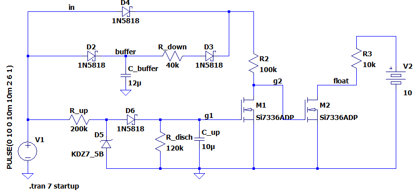
Without showing your circuit, it is hard to assess it. However, if precision is not so critical, you could use a circuit similar to the following to achieve a delay at power on and at power off. The supply voltage and time constant would have to be adapted to your case.

How it works.

  1. Upon switch on of the power supply, the floating node is pulled to ground through M2, R2 and D4.
  2. The R_up and C_up network begin to charge and so does the buffer capacitor C_buffer
  3. Once the RC(up) timer voltage is high enough, M1 is turned on, and the float node is no longer grounded.
  4. Once the supply voltage is interrupted, the C_up capacitor is quickly discharged through R_disch
  5. The C_buffer and R_down + R2 hold then the float node to ground for a time constant defined by their values.

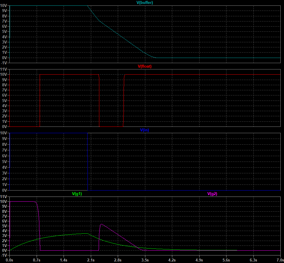
For simulatin purposes, the float node assumes that it is floating if it is pulled to 10V. Since you did not provide details about you voltage levels, I considered a working voltage of 10V.

enter image description here

waveform

\$\endgroup\$

Not the answer you're looking for? Browse other questions tagged or ask your own question.