4
\$\begingroup\$

I need to power a small SG90 servo motor. I could easily use a 5V battery but why bother? :) Aside from this not funny joke, I'd like to put to good use my little knowledge of electronics gained at University.

The datasheet of the servo does not mention any current draw (max, min, average, etc., ...). However I know that my USB port can barely handle Arduino with some sensor and a servo moving around so I guess it could easily be 100 mA. This figure is nothing I know, but it's a start at least. Furthermore the servo does not do any "heavy lifting" it just rotates a small aluminium bar which is super light. There should not be any "stuck" positions.

Since my main PS is a 12 V battery I thought I could step down the voltage using some resistors and then use an op amp (LM741) and a NPN transistor (2N3904) to set voltage and current, respectively. See the schematics below.

By using this circuit I should be able to output 100 mA while keeping the heat dissipation of the 2N3904 NPN within the admissible range of max 0.5 W. I guess I could even go up to 200 mA if I work around the circuit a bit more, however, before going on I ask myself and you, is this circuit able to handle such high current loads such a servo motor (i.e. do you see any flaw in this)?

Schematic

\$\endgroup\$
2
  • 1
    \$\begingroup\$ I'd just use a voltage regulator IC rather than trying to build my own... \$\endgroup\$
    – brhans
    Commented Jul 18, 2016 at 20:01
  • 1
    \$\begingroup\$ But to critique your circuit - if your motor did draw 100mA - what would the voltage drop across your 100R resistor be? Assuming that problem is resolved, reducing 12V to 5V requires a 7V drop somewhere & that somewhere will also be carrying your motor's 100mA - that's 0.7W, so something's going to need a heatsink. \$\endgroup\$
    – brhans
    Commented Jul 18, 2016 at 20:02

4 Answers 4

2
\$\begingroup\$

Although I haven't used the SG90 servo, most RC servos want to see about 6 Vdc with significant current capability.

Even though the servo might be lightly loaded, you still have to get the motor spinning everytime the servo begins to move. The motor stall current can be significant - anywhere from several hundred mA all the way to to several Amps.

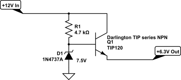
Because the servo is lightly loaded, you can probably get away with a really simple linear regulator. The simplest such regulator is a simple Zener diode followed by a series-pass current-boost transistor.

Something that I have used in the past is as follows:

schematic

simulate this circuit – Schematic created using CircuitLab

This is good for up to 1 Amp or more for brief surges and is perfectly adequate for powering a RC servo. Note that the regulation is fairly lousy but the servo won't mind.

[Edit]

Someone commented that this servo doesn't want to see more than 5V. This is an easy fix: simply change the Zener diode to a 6.2V part instead of 7.5V. That would be 1N4735 or 1N5234. This will provide a nominal 5V output.

\$\endgroup\$
1
  • 1
    \$\begingroup\$ Datasheet says: 4.8V (~5V), so I would not give it 6.3V... \$\endgroup\$
    – dpdt
    Commented Jul 18, 2016 at 20:17
2
\$\begingroup\$

Don't reinvent the wheel, just get a voltage regulator. Digikey sells efficient switching stepdown regulators that will output 5V @several amps (like this one). You can probably get one for < $10, all parts included.

For your circuit, I would be concerned about R3. If you want to output 0.1A, the voltage drop across a 100 ohm resistor is going to be 10V. 12V - 10V = 2V. Also, there's probably going to be other problems that I haven't foreseen yet (I'm not an expert on voltage regulator design).

\$\endgroup\$
2
\$\begingroup\$

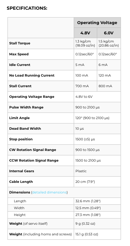
For completeness, here are the specifications of the SG90 (from FEETECH (Fitec) FS90 9G Mini Servo with Accessories), showing the current draw, at idle, no load and stall:

SG90 specifications

The FG90 is similar in specification to the SG90. From the website:

The FS90 is a 9 g analog servo from FEETECH (formerly known as Fitec) which is similar in form and function to the Towerpro SG90. The specifications state that this servo has a 120° operating angle for standard servo pulses between 900 µs and 2100 µs. As with most servos, the pulse range can be expanded to achieve an expanded operating angle, but the limits of which are not specified by FEETECH.

\$\endgroup\$
1
\$\begingroup\$

The rated current for a SG90 is 220 ±50mA, stall 650 ±80mA. So budget on 270mA worst case. A simply 12V/5V BUCK should handle this and be relatively small. (long link) Check www.aliexpress.com for Mini360 or similar.

\$\endgroup\$
1
  • \$\begingroup\$ Will the modules in question simply shut down if the servo does jam/stall? Also, are they documented at all? \$\endgroup\$ Commented Nov 12, 2017 at 19:20

Your Answer

By clicking “Post Your Answer”, you agree to our terms of service and acknowledge you have read our privacy policy.

Not the answer you're looking for? Browse other questions tagged or ask your own question.