Your transmitter and receiver use ASK - Amplitude Shift Keying type of modulation. This means that when you input a "1" to the transmitter that it is producing the carrier wave at 434 MHz continuously. When you input a "0" to it there is no carrier wave produced.
You are likely correct that there is a filer involved, likely in the receiver, which is cutting off the constant carrier it is receiving when you are transmitting a "1", and the xmitter is therefore continually producing the carrier. This would be a high-pass filter, not a low-pass filter.
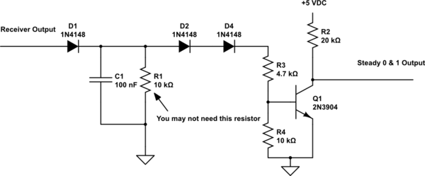
So, I think you can get around this problem by simply pulsing the transmitter on and off with something like a 555 timer set to an arbitrary low frequency - say 1,000 Hz - when you want to transmit a "1". Then on the receiving end merely half-wave rectify the output of the receiver with a low frequency signal diode (e.g. 1N914 or 1N4148), and a small filter cap (approximately 0.1 Mfd ceramic), and perhaps a bleeder resistor as shown in the schematic below. This will turn the 1,000 Hz ASK modulation into a steady high level, signifying the reception of a "1".
When you "transmit" a "0" the receiver will output approximately 0.0 volts, so the half-wave rectifier will output a steady 0.0 volts signifying reception of a "0". ( You are not really "transmitting" because there is no carrier!)
Since your "data" rate is so low (5 secs on, 5 secs off), the half-wave rectifier component values are not very critical. A little experimentation with different 555 frequencies at the transmitter end and half-wave capacitor values at the receiver end should yield workable results quickly.

simulate this circuit – Schematic created using CircuitLab
If your receiver suffers from some reasonable degree of random carrier noise acquisition, you might be able to filter out the resulting output noise pulses by adding D2,D4,Q1,R2,R3 & R4 to the basic half-wave rectifier circuit. Random noise will produce an average DC voltage across C1 of about 1/2 Vcc ( presumably 2.0 - 2.5 volts). D2,D4 and Q1 form a crude comparator which will only switch on (creating a low output) when the real 1K signal comes along. The lower you make the 555 modulating frequency, the better will be your noise immunity.

