0
\$\begingroup\$

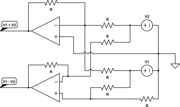
I have two signals, one is a baseline voltage (V1) and the other is a 'difference' voltage (V2). From these I want to produce two signals, V1 + V2 and V1 - V2. The circuit I currently have is:
schematic

simulate this circuit – Schematic created using CircuitLab
Where R is the same everywhere.

Based on the diagrams found here:
http://www.electronics-tutorials.ws/category/opamp

Using This Op-Amp

I have a feeling something about this is wrong, and I can't just drive both a summing and differential amplifier in parallel. If so, can someone give me advice on how to get both of these voltage values with just the two inputs?

\$\endgroup\$
4
  • \$\begingroup\$ a rather awkward schematic but essentially ok, disregarding CM gain on ground noise. try to stick with conventions on drawing std. patterns \$\endgroup\$
    – D.A.S.
    Commented Nov 8, 2016 at 5:31
  • \$\begingroup\$ Your "summing" amplifier is in an inverting configuration; the output is not \$V_1 + V_2\$ but \$-(V_1 + V_2)\$ \$\endgroup\$
    – Ben Voigt
    Commented Nov 8, 2016 at 6:12
  • 3
    \$\begingroup\$ Notice how both answers have schematics drawn left to right. This makes life so much easier for readers. Engineers 'read' schematics much as everybody reads text. !difficult unneccessarily it's but, here written I've what out work can You \$\endgroup\$
    – Neil_UK
    Commented Nov 8, 2016 at 6:52
  • 1
    \$\begingroup\$ even Asians follow universal rules, dont let Right to left writing in your language affect your ability to be understood by the ROTW \$\endgroup\$
    – D.A.S.
    Commented Nov 8, 2016 at 12:35

3 Answers 3

2
\$\begingroup\$

You can drive two amplifiers in parallel as long as you don't load the inputs too much (choose your resistor value in consideration of the drive strength of your signal sources).

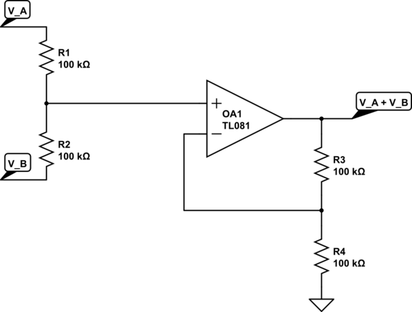
You need a different summing amplifier circuit in order to get a non-inverting sum, however. Try a simple voltage divider connected between the two inputs, the result is the average of the input signals \$\frac{V_1 + V_2}{2}\$. Connect this to the positive terminal of an non-inverting amplifier with a gain of 2.

schematic

simulate this circuit – Schematic created using CircuitLab

The differencing circuit you have now looks ok.

\$\endgroup\$
0
\$\begingroup\$

This may help:

schematic

simulate this circuit – Schematic created using CircuitLab

This can be realized with 4 opamps.

Instead of using LMx58, I recommend using TL074 (single IC, 4 opamps) with dual (e.g. ±12V) supply.

\$\endgroup\$
0
\$\begingroup\$

I have a feeling something about this is wrong

Your "sum" amplifier produces an inverted output -(b+a). Ben has pointed out a possible alternative strategy that will give you (b+a)

and I can't just drive both a summing and differential amplifier in parallel. If so, can someone give me advice on how to get both of these voltage values with just the two inputs?
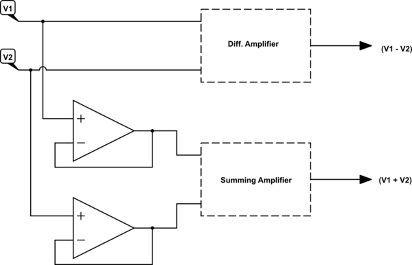
There are a number of questions you need to ask yourself before you can even begin on a design like this.

  1. What is the impedance of your input signal sources.
  2. To what level is it acceptable to load the inputs.
  3. Is it ok if the loading on one input depends on the voltage currently present on the other input potentially causing input to input crosstalk?
  4. How accurate do the calculations need to be.
  5. What frequency does this all need to work at.

Depending on your answers to these questions the soloution may turn out to be very easy or very difficult.

\$\endgroup\$

Your Answer

By clicking “Post Your Answer”, you agree to our terms of service and acknowledge you have read our privacy policy.

Not the answer you're looking for? Browse other questions tagged or ask your own question.