I am trying to solve this circuit and am getting confused by how the input impedance of the base of the transistor is calculated. I am confused how this is done? What are the general rules for figuring out the input impedances when looking into the base, emitter or collector? Do I need to rely on small signal models?
-
1\$\begingroup\$ Do I need to rely on small signal models? Oh yes definitely ! Input impedance is a small signal parameter so you need to evaluate it using the small signal equivalent circuit. But beware of that answer of 190 kohm, as seen from Vin, Rin cannot be that high as R1 // R2 is already 50 kohm. \$\endgroup\$– BimpelrekkieCommented Nov 10, 2016 at 10:02
-
\$\begingroup\$ Can you point me to some resources where I could understand how they derive that type of equation? Thanks! \$\endgroup\$– EasyOhmCommented Nov 10, 2016 at 10:05
-
\$\begingroup\$ This circuit is a "common collector" (the collector is grounded in the small signal sense), google that and you'll find plenty of explanations. This is standard stuff for aspiring EEs so taught at every decent technical University. For example: people.seas.harvard.edu/~jones/es154/lectures/lecture_3/… and leachlegacy.ece.gatech.edu/ece3050/notes/bjt/ccamp.pdf \$\endgroup\$– BimpelrekkieCommented Nov 10, 2016 at 10:07
-
\$\begingroup\$ That equation calculates 5k || 3k and reflects that back to the base but increased by the current gain of the transistor. Just look up product over sum for parallel resistors. \$\endgroup\$– Andy akaCommented Nov 10, 2016 at 10:21
-
\$\begingroup\$ In the given expression for Rin (it is better to write "rin" because it is a dynamic small-signal parameter) the base-emitter resistance rbe is missing (see my answer). \$\endgroup\$– LvWCommented Nov 10, 2016 at 14:53
2 Answers
What are the general rules for figuring out the input impedances when looking into the base, emitter or collector?
These are general rules: -
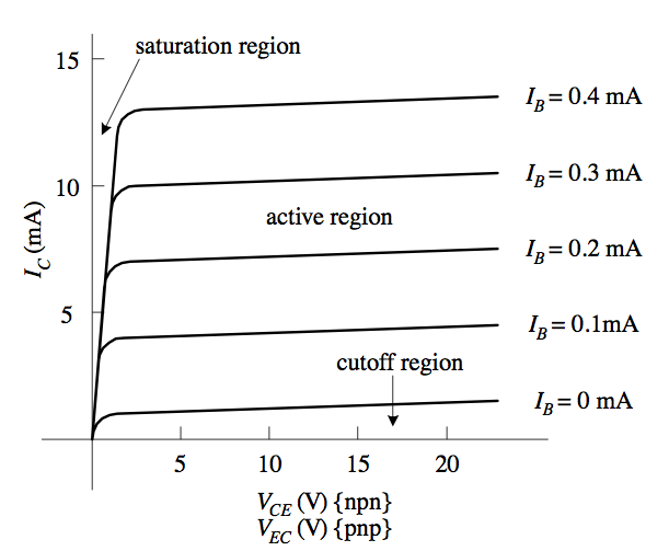
Looking into the collector you will generally find a high impedance (assuming the transistor is operating linearly in the "active region"): -
In the active region you can see that if you increase Vce the collector current only rises a small amount. Look at the graph where base current is 0.3 mA; when Vce is 5V, Ic is about 10 mA and, if you increased Vce to 20 volts maybe Ic has increased to 10.5 mA. So, there is a dynamic impedance of 15 volts divided by 0.5 mA and, this is a dynamic resistance of 30 kohm.
If you look into the emitter you will find a harder place impedance wise and, as a general simple rule, the impedance is just a few tens of ohms - think about an emitter follower - it has a low output impedance (the same as the input impedance looking in) because if the load impedance reduced, then the base-emitter would turn on a tad more and the collector current would compensate this by keeping the voltage at the emitter nearly the same.
When looking into the base you have to consider the emitter resistor and, in an emitter follower circuit, this emitter resistor is sometimes loaded with another resistor such as in the picture in the question.
So, the emitter resistor becomes Re||Rload or \$\dfrac{R_e.R_{load}}{R_e + R_{load}}\$ and this should start to look familiar as being part of the equation in your question. Because of current gain this combined emitter resistance is transferred to the base by multiplying by hFE. Ultimately the impedance you calculate will be in parallel with the base bias resistors so there is another step to calculate input impedance rather than just the impedance looking into the base.
Input resistance at the base node:
It is a rather straight-forward procedure - starting with the definition of the input resistance: rin=Vin/Iin=Vb/Ib with Iin=Ib and Vin=Vb.
Using the base-emitter differential resistance rbe=h11=1/yie we can write
In=Ib=Vbe/rbe=(Vb-Ve)/rbe=Vb/rbe - IeRe/rbe (Re=Remitter||Rload)=5k||3k).
Ib=Vb/rbe - Ib(hfe+1)Re/rbe (because Ie=(hfe+1)Re ; hfe=beta).
Vb/rbe= Ib[1+(hfe+1)]Re/rbe
rin=Vb/Ib=rbe+(hfe+1)Re.
This input resistance rin at the base node is in parallel to both ohmic voltage divider resistors R1||R2.
EDIT: The differential resistance rbe=hie can be found using the transconductance gm=Ic/Vt=hfe/hie. Solving for rbe gives: rbe=hie=hfe*Vt/Ic.


