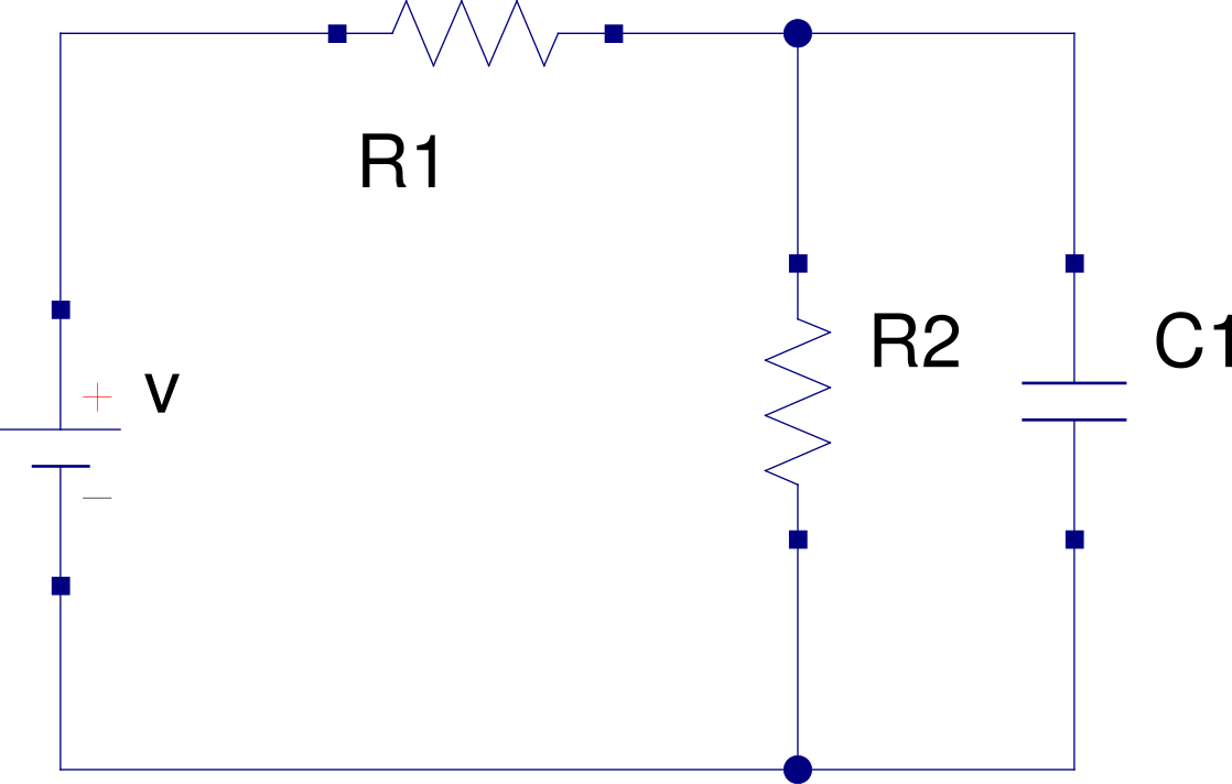
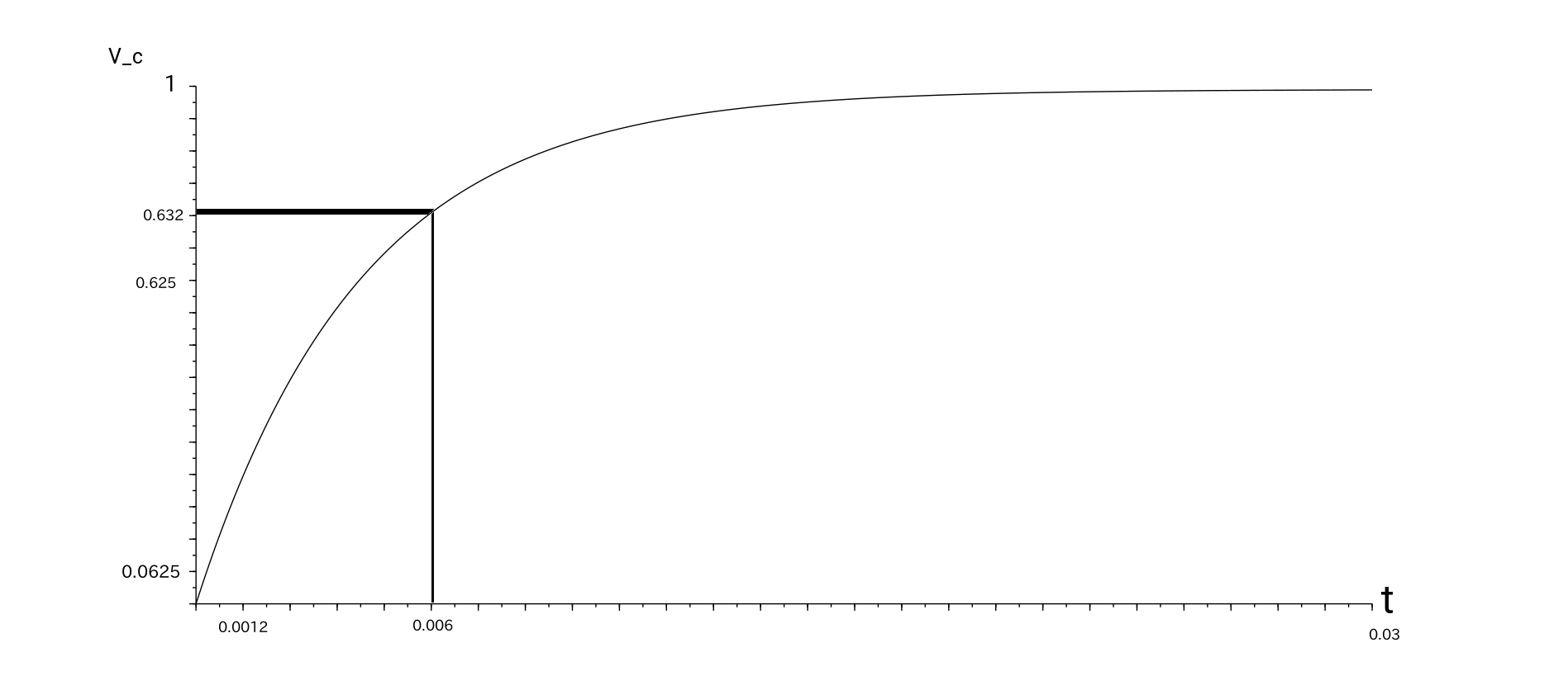
My first instinct would be to first apply Thevenin to \$V\$, \$R_1\$, and \$R_2\$ in order to reduce this to a simple series RC problem, whose solution is:
$$\begin{align*}
R_{th} &= \frac{R_1\cdot R_2}{R_1+R_2} = 5\:\textrm{k}\Omega\\
\\
V_{th} &= V\cdot\frac{R_2}{R_1+R_2} = \frac{1}{2}\:V \\
\\
\tau&= R_{th} \cdot C_1 = 6\:\textrm{ms}\\
\\
V_x=V_{R_1}&=V_{th}\cdot\left(1-e^{-\cfrac{t}{\tau}}\right)=\frac{1}{2}\:V\cdot\left(1-e^{-\cfrac{t}{\tau}}\right)
\end{align*}$$
But that's not a general approach. It just works in this case.
Nodal analysis is way, way more general and would be, setting the bottom node arbitrarily to \$0\:\textrm{V}\$:
$$\begin{align*}
\frac{V_x}{R_1} + \frac{V_x}{R_2} + C_1\frac{\textrm{d} V_x}{\textrm{d} t}&= \frac{V}{R_1} + \frac{0\:\textrm{V}}{R_2} \\
\\
V_x\cdot\left(\frac{1}{R_1} + \frac{1}{R_2}\right) + C_1\frac{\textrm{d} V_x}{\textrm{d} t}&= \frac{V}{R_1} \\
\\
\frac{\textrm{d} V_x}{\textrm{d} t}+\frac{1}{C_1\frac{R_1\cdot R_2}{R_1+R_2}}V_x&= \frac{V}{R_1 C_1} \\
\\
\frac{\textrm{d} V_x}{\textrm{d} t}+\frac{1}{C_1 R_{th}}V_x&= \frac{V_{th}}{C_1 R_{th}}
\end{align*}$$
Which is in a very familiar first-order ODE form. You can apply Laplace to that.
But just using the usual ODE solution method for first-order, gives:
$$\begin{align*}
P_t = \frac{1}{C_1 R_{th}},~~Q_t &= \frac{V_{th}}{C_1 R_{th}},~~\therefore~~ \frac{\textrm{d} V_x}{\textrm{d} t}+P_t V_x= Q_t\\
\\
\mu &= e^{\int P_t\:\textrm{d} t} = e^{\left[\cfrac{t}{C_1 R_{th}}\right]}\\
\\
V_x &= \frac{1}{\mu}\int \mu\: Q_t~ \:\textrm{d} t \\
\\
&= e^{\left[\cfrac{-t}{C_1 R_{th}}\right]}\int e^{\left[\cfrac{t}{C_1 R_{th}}\right]}\: \frac{V_{th}}{C_1 R_{th}}~ \:\textrm{d} t \\
\\
&= e^{\left[\cfrac{-t}{C_1 R_{th}}\right]}\cdot \left(\frac{V_{th}}{C_1 R_{th}}\right)\cdot \int e^{\left[\cfrac{t}{C_1 R_{th}}\right]}\:~ \:\textrm{d} t \\
\\
&= e^{\left[\cfrac{-t}{C_1 R_{th}}\right]}\cdot \left(\frac{V_{th}}{C_1 R_{th}}\right)\cdot \left(C_1 R_{th}\: e^{\left[\cfrac{t}{C_1 R_{th}}\right]}+C_0\right) \\
\\
&= V_{th}\:e^{\left[\cfrac{-t}{C_1 R_{th}}\right]}\cdot \left(e^{\left[\cfrac{t}{C_1 R_{th}}\right]}+C_0\right) \\
\\
&= V_{th}\left(1 + C_0\:e^{\left[\cfrac{-t}{C_1 R_{th}}\right]}\right)
\end{align*}$$
Using the initial condition that \$V_x\left(t=0\right) = 0\:\textrm{V}\$, this results in \$C_0=-1\$, so:
$$\begin{align*}
V_x &= V_{th}\left(1 -e^{\left[\cfrac{-t}{C_1 R_{th}}\right]}\right) = \frac{1}{2}\:V\cdot\left(1-e^{-\cfrac{t}{\tau}}\right)
\end{align*}$$
And now you can see why the Thevenin approach would be chosen first.
Or use Laplace applied to the ODE mentioned earlier. Using the known initial condition, you get \$Y_s = \frac{Q_t}{s^2+P_t s}\$, which solves out as \$y_t=\frac{Q_t}{P_t}\left(1-e^{-P_t t}\right)=V_{th}\left(1-e^{\frac{-t}{\tau}}\right)=\frac{1}{2} V\left(1-e^{\frac{-t}{\tau}}\right)\$.
Of course, knowing \$V_x\$ it is trivial to then answer your title question regarding the current in \$R_1\$ over time.
 calculate the current in \$R_{1}\$, $$R_{1}=R_{2}=10k\Omega $$ and $$C=1.2\mu F$$. Well, I have two approaches.
