0
\$\begingroup\$

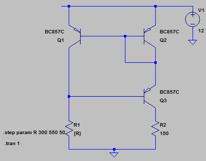
I am trying to understand simple wilson current mirror circuit for regulating LED current based on external input.

Below is my challenge:
based on the value of the R1 resistor the current through the load R2 is to be changed. Current i am planning to pass through the load is about 20 mA to 50 mA.

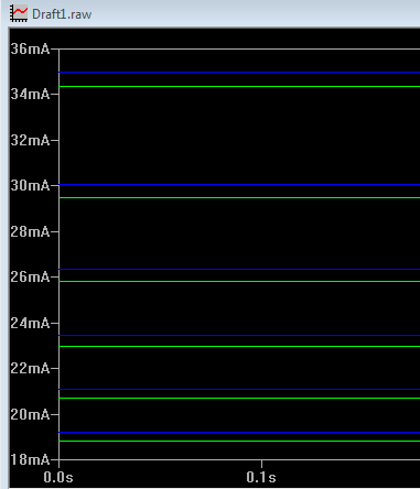
Case1:: R1 ranges from 300 to 550. R2 set to 100 ohms. Below are the simulation results.

R2 set to 150 ohms R1 varies from 300 to 550 ohms

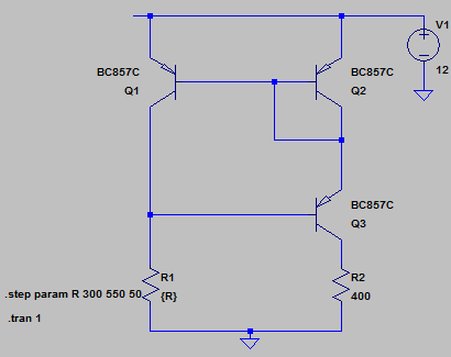
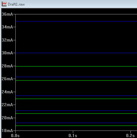
Case2: R1 range is same as above. R2 is set to 400 ohms. Below are the results.

enter image description here enter image description here

My basic questions:
1. have i got the basic wilson circuit correct?
2. are the R1 and R2 values relative. For csae2 above, i see that, the current mirror is not successful. Is this because R2 is already bigger than R1?
3. Any guidance towards the relation between R1 and R2, and improvements if any are welcome.

Edit:
My goal: To control the flow of the current through R2 (between 20 to 50 mA). Finally, i will have a LED in place of R2 and a small protective resistor. i have to control the resistance R1, from which the LED current should get regulated. This exercise is to understand more about wilson current mirror too.

Edit2
Added LED TLCR51 info: http://www.farnell.com/datasheets/463614.pdf

Thanks in Advance.

\$\endgroup\$
10
  • \$\begingroup\$ Buy the book, "Current Sources & Voltage Reference," by Linden T. Harrison. It's kind of a combo history and survey of current sources and voltage references (related problems for IC manufacturers.) It includes some modest discussion about early problems in forming discrete current sources with parts that varied and some of the "fixes" that help to reduce the impact of mismatched \$\beta\$ and \$V_{BE}\$. Also, worth noting that there are BJT pairs available designed for things like this that are \$V_{BE}\$ matched (cheap) and both \$\beta\$ and \$V_{BE}\$ matched -- more expensive. \$\endgroup\$
    – jonk
    Commented Dec 8, 2016 at 20:12
  • \$\begingroup\$ Also, since you are interested in the Wilson, you may also want to note that there are two different "full Wilson" configurations, as well. And I think the Wyatt is another one worth a gander -- it's especially nice as it uses the positive tempco of metal film and/or aluminum to compensate BJT negative tempcos to produce a very stable source that works over a relatively wide range of source voltages and temperatures. \$\endgroup\$
    – jonk
    Commented Dec 8, 2016 at 20:16
  • \$\begingroup\$ Is your question about understanding? Or about a solution? \$\endgroup\$
    – jonk
    Commented Dec 8, 2016 at 20:17
  • \$\begingroup\$ @jonk I am looking forward to drive a couple of power LEDs with discrete constant current source circuit. \$\endgroup\$
    – User323693
    Commented Dec 9, 2016 at 6:49
  • \$\begingroup\$ Thanks. Then you don't care about understanding the Wilson current mirror, in particular. Just in understanding some kind of constant current circuit for power LEDs. You need to carefully specify exactly what kind of voltage and current is required for the power LEDs (how many, what arrangement, what do they require) and what power supply all this will be coming from (what rail voltage and current compliance does it offer?) It's either a major edit or else an entirely new question. \$\endgroup\$
    – jonk
    Commented Dec 9, 2016 at 7:22

1 Answer 1

1
\$\begingroup\$
  1. The circuit is correct. However it will not work very well in practice with discrete parts- the transistors will be mismatched in Vbe and temperature. It works well on a monolithic chip where the transistors are matched and kept at the same temperature. In simulation those effects do not show up by default.

  2. The current mirror will saturate if (approximately) R2>R1. 28mA*400\$\Omega\$ = 11.2V, leaving only 800mV across Q2+Q3.

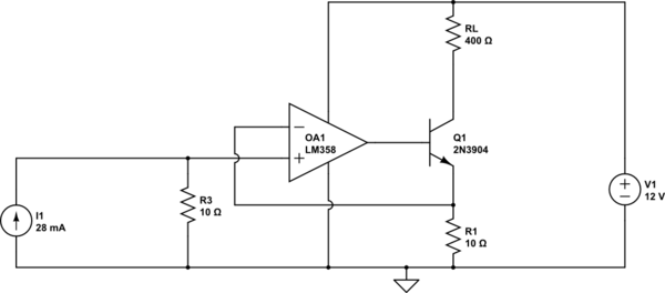
  3. Any improvements would depend on what exactly you are trying to accomplish. An LED does not behave like a resistor and this circuit does not really regulate the current to a set number, it just controls it roughly proportional to the input voltage minus a diode drop. A few penny op-amp and a transistor will do a much better job of that.


Edit: Example of the above:

schematic

simulate this circuit – Schematic created using CircuitLab

You can replace I1 with a resistor from R3 to +12 if you want to make the current proportional to the supply voltage.

\$\endgroup\$
3
  • \$\begingroup\$ my intention is to employ the wilson current mirror. In point#3, do you mean, current mirror circuit using opamp and transistor or simple regulated constant current circuit for LED? \$\endgroup\$
    – User323693
    Commented Dec 8, 2016 at 7:43
  • \$\begingroup\$ You can make a current mirror using an op-amp and a BJT (and two resistors), but it's not a Wilson mirror as you want, so it would be a waste of time to describe it. \$\endgroup\$ Commented Dec 8, 2016 at 7:46
  • \$\begingroup\$ I am really looking for the solution you proposed. can you share the brief idea too. please. \$\endgroup\$
    – User323693
    Commented Dec 8, 2016 at 8:22

Your Answer

By clicking “Post Your Answer”, you agree to our terms of service and acknowledge you have read our privacy policy.

Not the answer you're looking for? Browse other questions tagged or ask your own question.