0
\$\begingroup\$

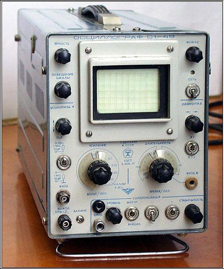
I'm at the point where I'm stuck on communication issue and thinking on finally getting an oscilloscope. To my beginner surprise, wasn't expecting them to be so extremely expensive, so I was looking around and found old school oscilloscope for super cheap.

The guy who is selling the scope is claiming it can be used for 'Arduino' projects, but I'm a bit skeptical about monitoring binary data with this.

Only thing I'm confused about is CPU MHZ vs BUS MHZ. The oscilator datasheet says

The amount of CRT rays: Single beam
Range of measured voltages: 20 mV - 200
The range of measured time intervals: 8 ms - 0.5 sec
Bandwidth: 0 - 5.5 MHz
Input channel resistance: 1 Mom
Input channel capacity: 50 pF
The minimum duration of the sweep: 0.2 ms / div
Maximum scan duration: 10 ms / div
Calibration voltage signal:  50 mV

enter image description here

I'm worried about '5.5 MHz'. For my current problem, I need to use it to detect TWI communication problem, since the BUS runs at 100khz or 400khz, then as far as I understood I can perfectly do this.

Now I don't understand what will happen if I try to measure output of the AVR pins directly (without TWI, just random blinking pins with few ms interval). Am I gonna face the following issues:

  • If my AVR is running at 8Mhz and doesn't have any sleep between the pin outputs, this oscilloscope won't be able to pick it up?

    Basically I can't use this oscilloscope to monitor ports if my AVR is running at higher than 4Mhz?

    Thank you!

EDIT: Another alternative I thought I could do is to take another ATMEGA328, enable ADC, and send the result over WIFI/Bluetooth, technically I could make a very simple oscilloscope myself, correct? The only issue 'displaying' the data, measuring it shouldn't give me any trouble, if I'm looking to measure AVR's? Thanks!

\$\endgroup\$
8
  • 2
    \$\begingroup\$ You might find this chart useful to understand whats going on: ni.com/cms/images/devzone/tut/image5134608495473274407.jpg \$\endgroup\$
    – PlasmaHH
    Commented Dec 9, 2016 at 11:20
  • 1
    \$\begingroup\$ Be aware you're looking at an analog scope which will not store anything. If you're triggering single-sweep to capture, for example, UART output, all you'll get is a single sweep that will remain on the screen, depending on the persistence of the phosphors, no more than a few seconds. You're better off looking at a "USB scope" which uses a PC for display and controls. \$\endgroup\$
    – DoxyLover
    Commented Dec 9, 2016 at 11:24
  • 1
    \$\begingroup\$ You might want to consider a basic logic analyser or something like a bus-pirate. \$\endgroup\$ Commented Dec 9, 2016 at 11:24
  • \$\begingroup\$ Thank you guys for the explanations! If I wanted to do my own 'logic analyzer' can I simply use AVR interrupts to capture the binary data from another AVR that runts at the same CPU speed? \$\endgroup\$
    – 0x29a
    Commented Dec 9, 2016 at 11:30
  • \$\begingroup\$ It depends how fast the signals are changing. Your poor mans logic analyzer will only capture one transition at a time and take a number of cpu cycles to note each change. If you got a lot of transitions at the same time or close to each other then the times and possibly order will be incorrect. If the rate of change of the inputs is slow in comparison to the clock speed then you'll be OK. So ultimately it depends on exactly what you want to do. \$\endgroup\$
    – Andrew
    Commented Dec 9, 2016 at 11:34

2 Answers 2

3
\$\begingroup\$

The bandwidth of a scope is the frequency at which the displayed signal starts to decrease relative to the actual input voltage (at a guess it's the 3dB point where the signal is halved but I've never double checked that).

So if you put a 1V peak to peak signal in at 10Hz the scope will show 1V peak to peak exactly as you'd expect since you are no where near the limit. If you put in the same amplitude at 5.5MHz you'd see 0.5V. If you put in 1V peak to peak at 100MHz (way above the limit) you'd see a constant 0V (the average voltage).

When looking at signals from the AVR you'd see the correct DC levels and unless they were switching very fast you would see the correct patterns however the corners would show up as being far more rounded than they really are, a 5.5MHz square wave would show up as a sine wave. Even something at 8 MHz would show up to a certain extent but I wouldn't trust the accuracy of any measurements at that point.

Generally you want the scope to have a lot more bandwidth than the frequency you are working with so that you can see glitches and noise spikes but how vital that is depends on the problems you are trying to track down.

However keep in mind that that scope is an old school analog system, it will be useless for picking up one off transitions or anything that isn't a constant pattern. For digital work on a budget a USB based software oscilloscope running on a PC is the best trade off of price and performance these days. Still no substitute for a good quality standalone scope but a LOT cheaper.

\$\endgroup\$
3
  • \$\begingroup\$ Thank you very much for explaining. I will look for an USB alternative or save some money for a modern scope. ) \$\endgroup\$
    – 0x29a
    Commented Dec 9, 2016 at 11:33
  • 1
    \$\begingroup\$ On a digital scope there are two things to look for - the bandwidth and the sample rate. Bandwidth is exactly the same as above. Sample rate is exactly what the name implies, the rate at which it samples the probes. Any signals that are more than half of the sample rate will either nor show up at all or be displayed incorrectly (they will alias down to a lower frequency) depending upon the bandwidth. The sample rate should always be at least twice the bandwidth but ideally more like 10 times the bandwidth. \$\endgroup\$
    – Andrew
    Commented Dec 9, 2016 at 11:39
  • \$\begingroup\$ I will keep that it mind ) Thank you so much for the detailed explanation! \$\endgroup\$
    – 0x29a
    Commented Dec 9, 2016 at 12:07
1
\$\begingroup\$
  1. If you're looking forward to only decode digital communications, then your best bet is trying a logic analyzer. That will only decode 0 or 1, but the software will usually allow you to decode a few digital protocols into more manageable bytes. An oscilloscope will also do fine, but you'll have to decode the bits manually.

  2. I've often found that a scope was more invaluable than a logic analyzer. A logic analyzer is great if you're having trouble configuring the comm ports, but won't let you easily debug slope or noise problems, and other things that aren't related to the digital domain, but to the analog part of the transmission. If you're beginning, I recommend going for the scope first.

  3. Unless you're trying to debug crystal problems, this 5.5MHz scope will handle the AVR's 8MHz just fine. Remember that even if you switch the pin with only one instruction, it will still need two instructions to make a cycle (flip on and off). That will get you a 4MHz base signal. On the other hand, if the scope filters harmonics, what you'll see will be a filtered signal, probably smoother than what's actually being sent. You may also see some ringing that possibly isn't there because the real signal has higher-order harmonics to be squarish. Note: hardware communications usually don't operate in the same speed as the MCU, requiring some divider to work its multiple stages. I don't remember the Arduino datasheet to give you an exact divider number.

  4. In the long run, I recommend trying to find a Rigol 1052 scope (50MHz, with some models hackable to allow 100MHz signals). They used to be cheapish, but are great. Another option is the Analog Discovery 2 or even version 1 if you can find a used one. You may also consider the DSO Quad (the older DSOs have ~1MHz range). Its 72MSps may get you theoretically up to 36MHz, though for practical purposes it's probably lower, but should read 8MHz just fine.

\$\endgroup\$

Your Answer

By clicking “Post Your Answer”, you agree to our terms of service and acknowledge you have read our privacy policy.

Not the answer you're looking for? Browse other questions tagged or ask your own question.