7
\$\begingroup\$

I've been trying to understand EMF, specifically back EMF in electrical motors, such as for example a setup like this:

simple electrical motor

Say that we apply a voltage to the brushes. I understand that once the rotation gets going, a current will be induced by the changing flux inside the loop, and that this induced current is opposite to the current created by the external voltage. My understanding is that this results in a smaller net current in the loop, and this phenomenon is called back EMF.

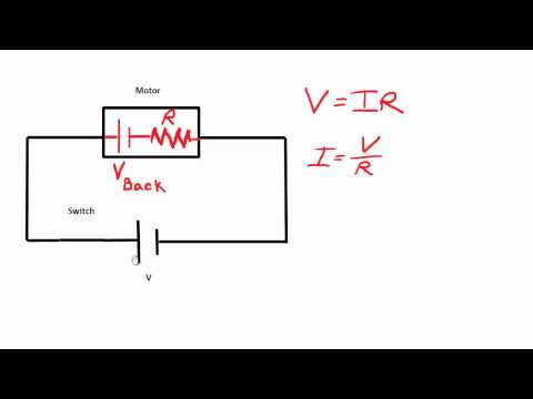
However, I don't exactly understand "where" the EMF (which is a voltage?) appears. One explanation I've seen is this:

motor circuit

where the EMF appears as a voltage source in series with the motor resistance. While this may be a good way to explain how the current will behave, it doesn't seem to explain what actually goes on inside the motor. Surely, the EMF doesn't appear "before" the motor, but rather inside it. Should it then somehow be seen as being superimposed on the resistor? Where, in the first figure, would the EMF appear? Does it change the voltage across the brushes? Where does the "extra" voltage drop happen?

\$\endgroup\$
1
  • \$\begingroup\$ It appears across the motor terminals. You can measure it by connecting a voltmeter across the terminals and, while the motor is running, removing the supply voltage. You'll then see the back emf reducing as the motor slows down. Alternatively, drive the motor with PWM and look at the terminal voltage using a scope - the back emf will be seen during the PWM off periods. \$\endgroup\$
    – Chu
    Commented Dec 30, 2016 at 15:33

5 Answers 5

14
\$\begingroup\$

The back EMF is generated in the wire that makes up the coils of the motor. When a wire is swept sideways thru a magnetic field, a voltage is generated along the length of the wire. Spin the motor with just a voltmeter connected, and you will see it make a voltage.

So yes, the resistance and the back EMF are actually distributed along the wire in the coil. There are lots (infinity, actually) of little resistances in series that each get a little voltage in series with them when the motor turns.

Viewed electrically from the outside, this can't be distinguished from a lumped resistance in series with a lumped voltage source. Since this is simpler to draw, think about, and analyze, that's how motors are usually shown.

\$\endgroup\$
7
  • 2
    \$\begingroup\$ +1 for an identical answer happy xmas etc.. and I think the bowler hat suits you Olin lol \$\endgroup\$
    – Andy aka
    Commented Dec 30, 2016 at 14:38
  • \$\begingroup\$ I think it's the part with the infinitely many little resistances I have trouble grasping. The EMF causes the current through these resistors to decrease, right? Decreased current implies decreased voltage. So where does the rest of the voltage go? \$\endgroup\$ Commented Dec 30, 2016 at 14:49
  • 1
    \$\begingroup\$ @Dan: No, the back EMF doesn't inherently cause a current thru the resistor. Think of the many distributed resistors and voltage sources as being in series, not in parallel with each other. The voltage is created when the motor spins, regardless of how it was made to spin. If you drive the shaft externally, then you can see that voltage directly. If you spin the motor by applying external voltage, the little voltage sources appose the applied voltage. This means the motor "sees" less applied voltage the faster it spins. \$\endgroup\$ Commented Dec 30, 2016 at 14:57
  • 1
    \$\begingroup\$ @Dan: Yes - - - \$\endgroup\$ Commented Dec 30, 2016 at 15:05
  • 1
    \$\begingroup\$ @Andy Right, but spatially the voltage is interspersed throughout the wire, not next to it. From a circuit perspective it obviously doesn't matter, but to understand the physics it sure does :) \$\endgroup\$ Commented Dec 30, 2016 at 15:36
3
\$\begingroup\$

You can simplify things by removing the battery from that diagram, and turning the motor by hand, as a generator.

As the armature turns, the wires cut through the magnetic field, and a voltage is generated in them.

This voltage is the same whether the armature is turned as a generator, or as a motor. When it's turned as a motor, this voltage is called the 'back EMF'.

\$\endgroup\$
0
3
\$\begingroup\$

Think of it like a generator; you spin the rotor and an output voltage is produced. This voltage is in series with the rotor coil. It makes no difference if instead of manually spinning the motor you apply dc to turn it.

\$\endgroup\$
2
  • \$\begingroup\$ +1 and happy new year. The bowler is one of the secret hats, so I don't know what I did to earn it. I'm not so sure the pink fluff suits you as well, but it's fun though. \$\endgroup\$ Commented Dec 30, 2016 at 14:45
  • \$\begingroup\$ @OlinLathrop Its the "Like Clockwork" hat (from the novel and Stanley Kubrick film). Not sure what it means, but my guess you got it for answering at least one question a day. \$\endgroup\$ Commented Dec 30, 2016 at 21:03
1
\$\begingroup\$

The back EMF "appears" across the slip ring brushes. Its polarity is such that it always opposes the "driving" voltage, causing a lower current draw than "normal." The "normal" current is found by locking the rotor and measuring the current drawn, then the rotor is allowed to rotate and the "running" current will be less than the "normal" current, due to the back EMF.

\$\endgroup\$
1
\$\begingroup\$

Good question: This is actually not so easy! It has taken me days to understand. Thanks to your pedagogic picture I finally got it!

You need to view it is as if the battery was disconnected from the circuit. So, you have a circuit without current running through it to start with. You spin the coil clockwise with your hands in the same way it would spin if the current was on. In the position you have made your drawing you have the right side of the coil moving downwards. So, you have the wire of the coil moving downwards, which means that also the positive charges in the wire coil are moving downwards (but not moving along the wire). With the rigth-hand-rule no. 1 you point your thumb downwards in the direction of moving charges, while at the same time you have your fingers pointing to the right along the magnetic field. Then you get a force from the palm of your hand pointing along the coil wire towards yourself in the picture. That is, you have positive charges (current in other words) moving in the wire towards the right-hand side brush.

So, you get a surplus of positive charges on the right brush, and surplus of negative charges on the left brush. So, you have gotten yourself an emf that works like a DC battery. The voltage potential of the emf is opposed the original emf created by the DC batteries. This creates a current through the circuit in the below part of the picture which is opposite in direction to the applied current by the DC batteries. As you turn the DC batteries on, you get a current that wants to go from right to left in the coil at the same time as it wants to go from left to right by the induced back emf. The faster you spin the coil with the DC current, the stronger the opposing back emf force will be also at the same time! So, this back emf always works against you.

\$\endgroup\$
2
  • 1
    \$\begingroup\$ You get the same result if you use lenz law. Magnetic flux opposed to the original flux through the coil. With the RHR-1 with current in the same direction as it is originally, but with magnetic field lines in the opposite direction you get the force on the coil to make it spin in the anti-clockwise direction. So, this is not completely analogous to the first thinking above, but ending up with the same result though. \$\endgroup\$ Commented Feb 6, 2019 at 7:11
  • \$\begingroup\$ I'm glad I'm not the only one who took days to understand this haha. The more I thought about it the more confusing things got... I finally figured it out though! \$\endgroup\$
    – mrbean
    Commented Mar 27, 2022 at 23:59

Your Answer

By clicking “Post Your Answer”, you agree to our terms of service and acknowledge you have read our privacy policy.

Not the answer you're looking for? Browse other questions tagged or ask your own question.