1
\$\begingroup\$

I want to compare power consumption of two devices powered by 9V batteries. One uses a buck converter and the other uses a linear regulator. Depending on their modes, these can draw between ~5-500 mW (~0.56-56 mA).

The way I would normally think to do this is to put a small resistor (~1 ohm) in series with the device's power supply and measure the voltage across that to determine current. Then, power would be found by multiplying current by supply voltage.

My concern is that the small resistor could potentially change the power consumption of the devices. I figure this effect would be tiny at low current draw but possibly significant at ~50 mA.

Plus, it's tricky for me to measure low voltages precisely: my multimeter has mV precision (ok at ~50 mA draw, not so good at 1 mA).

Is there a good way to measure power that I'm missing? Ideally, something accessible to a small lab without expensive equipment?

\$\endgroup\$
5
  • \$\begingroup\$ Low cost solution: current clamp + multimeter. High ems solution: Keithley 2281S battery simulator. \$\endgroup\$
    – winny
    Commented Jan 11, 2017 at 19:06
  • 1
    \$\begingroup\$ @Vulcan You have the right idea. . Normally a 50mV current shunt is used for full scale, which is gives enough to be sensed without dropping much voltage or dissipating much power.. i.e. efficient yet sensitive enough for DMM. It can be put on either V+ or 0V side for single probe measurements. Due to low battery high ESR, the SMPS pulse voltage drop will be more significant on transients and may affect dropout. Low ESR Caps can reduce this if f is high enough. i.e. Zc(f) is lower than ESR of battery. \$\endgroup\$
    – D.A.S.
    Commented Jan 11, 2017 at 19:18
  • \$\begingroup\$ sounds like maybe you want to build a transimpedance amplifier, for 60 mA you'll need a fairly strong op-amp. \$\endgroup\$ Commented Jan 11, 2017 at 19:20
  • \$\begingroup\$ to get a 3 decade range with at least 2 significant figures requires a 5 digit measurement or choose 1.5 sigfigs or 2 gain ranges. For a quick and dirty measurement, an Op AMP with a gain of 100 on 50mV and offset null, \$\endgroup\$
    – D.A.S.
    Commented Jan 11, 2017 at 19:22
  • 1
    \$\begingroup\$ Change Current Sense R with a switch during each events. to extend the range. 1 Ohm for 50mA and 100 Ohm for 500 uA range. Battery ESR starts around 10 ohms and rises with state of discharge to > 1k \$\endgroup\$
    – D.A.S.
    Commented Jan 11, 2017 at 19:31

1 Answer 1

3
\$\begingroup\$

You're on the right track: use a low resistance current sense resistor and measure the voltage. But most DMM's most sensitive setting is still high at 200 mV.

You can use a simple current sense amplifier to make the measurement super easy. These amplifiers convert current flowing through a sense resistor into an output voltage referenced to GND so the output voltage indicates measured current.

Linear Tech, Maxim, and others make them. Here's a simple example using the LTC6106:
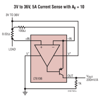
enter image description here

The way it works is that it pulls current into its -IN pin until -IN is at the same voltage as +IN. This current gets applied to the resistor on the OUT pin, and that current creates a higher voltage which you can then you can read with a DMM or ADC.

With this amplifier, your DMM can become a very sensitive current measurement tool.

It's easier to understand with example numbers:

Let's say 1 Amp is flowing through the 0.02 Ohm sense resistor to the load. This creates 20 mV across the resistor. The amplifier will pull current into -IN through the 100 Ohm mirror resistor until it sees the same 20 mV drop.

This means the current through the 100 Ohm is 20 mV / 100 = 0.2 mA. So basically that 1 Amp has been converted to a 0.2 mA current.

Now the same 0.2 mA current flows into the 1 kOhm output resistor, so the voltage at OUT is 0.2 mA * 1 kOhm = 0.2 Volts, which you can easily measure with your DMM.

So using these resistor values, the gain of the system is 1 Amp = 0.2 Volts output.

Now that you know how it operates, you can adjust the resistor values to more suit your application. Read the datasheet to understand its limitations and recommendations. For example, there's a minimum voltage it needs to operate, there's a minimum value you should use for the input resistor, a maximum recommended output current, etc.

Also, don't forget your DMM will load down the output resistor slightly. For example, if your DMM has 1 MOhm impedance, this is basically having 1 MOhm in parallel with the 4.99k output resistor. I hope that helps. Happy tinkering, -Vince

\$\endgroup\$
2
  • \$\begingroup\$ Thanks Vince, but my question would be if we want to meausure current, voltage, current, power factor in power in AC. This LT6106 change the waveform or the angle. Thanks in advance \$\endgroup\$
    – Bill B
    Commented Aug 3, 2017 at 22:59
  • \$\begingroup\$ Hi Bill, woah, that was really confusing. The original post was saying 9V DC power and you're asking about power factor in AC. I finally realized you're not the OP (original poster). Would be best if you posted a new question instead. Otherwise we'd have a long comment chain on something only vaguely related to the origina post. \$\endgroup\$ Commented Aug 4, 2017 at 20:11

Your Answer

By clicking “Post Your Answer”, you agree to our terms of service and acknowledge you have read our privacy policy.

Not the answer you're looking for? Browse other questions tagged or ask your own question.