1
\$\begingroup\$

I'm interested in measuring the efficiency of a loudspeaker. I have tools to measure the SPL in dB. However, the electrical efficiency has me a little puzzled.

The speaker has a voltage applied: \$V_{spk}\$. It also has a resistance: \$R_{spk} = 8 \Omega\$. However, it should also have an inductance, giving it a complex impedance.

What is a simple way to measure the electrical power consumption? Do I need to measure the inductance and compute the current? Won't putting a resistor in series to measure current with an oscilloscope probing the resistor cause both grounding problems and change the overall impedance and power consumption?

This must be done in industry all the time... shouldn't there be an easy way?

\$\endgroup\$
2
  • \$\begingroup\$ Well, in industry, you might use a current probe. However, that's not exactly simple if you don't have a current probe. Also, keep in mind that the resistance of the speaker really isn't 8Ω, except maybe at one or two frequencies. \$\endgroup\$
    – uint128_t
    Commented Mar 7, 2016 at 22:58
  • \$\begingroup\$ I always thought that nominal speaker impedance was measured at 400Hz, but according to Wikipedia there are at least another 2 ways of specifying it. \$\endgroup\$
    – Steve G
    Commented Mar 7, 2016 at 23:03

4 Answers 4

2
\$\begingroup\$

schematic

simulate this circuit – Schematic created using CircuitLab

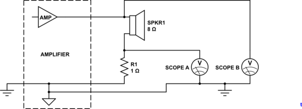
Figure 1. Test setup avoiding earth-shorts.

Figure 1 shows one way of making the measurement and avoiding the grounding problems. It does suffer from the disadvantages of modifying the circuit under test as you pointed out in your question.

Note that even this setup could have problems if there are high currents in the return wire as this will raise the voltage and some of the current may return through the scope ground and the mains earth wiring.

Ground reference for the oscilloscope must be on the star ground point of the amplifier to avoid the oscilloscope reads the voltage drop on the speaker return wire. (As commented by soosai steven.)

\$\endgroup\$
5
  • \$\begingroup\$ Ground reference for the oscilloscope must be on the star ground point of the amplifier to avoid the oscilloscope reads the voltage drop on the speaker return wire. \$\endgroup\$ Commented Mar 7, 2016 at 22:30
  • \$\begingroup\$ If you have a good enough scope you may be able to use a 0.1 Ohm measurement resistor. \$\endgroup\$
    – Steve G
    Commented Mar 7, 2016 at 23:02
  • \$\begingroup\$ @soosaisteven: Good point. I've modified the schematic and added your comment. \$\endgroup\$
    – Transistor
    Commented Mar 7, 2016 at 23:33
  • \$\begingroup\$ I don't think I have a signal return and an earth ground. Are you suggesting I connect the resistor to the return and the scope to earth ground on the amp? or can I just make sure they are both connected at chassis ground through the 3rd prong in the outlet? \$\endgroup\$ Commented Mar 8, 2016 at 2:02
  • \$\begingroup\$ If the amplifier has only a 2-wire connection to the mains then it is "floating" with respect to earth and you can connect any single part of the speaker circuit to 'scope ground as shown in Bruce Abbott's answer. Does that make sense? \$\endgroup\$
    – Transistor
    Commented Mar 8, 2016 at 6:32
0
\$\begingroup\$

There are other ways to measure current besides shunt resistors, such as hall effect current transducers, which detect the magnetic field created by the current passing through the wire. If you can sample that and the applied voltage at high enough frequency, you should be able to calculate the average power consumption.

\$\endgroup\$
0
\$\begingroup\$

Won't putting a resistor in series to measure current with an oscilloscope probing the resistor cause both grounding problems and change the overall impedance and power consumption?

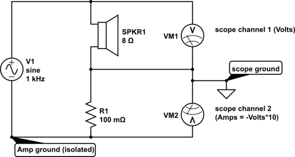
It won't cause a grounding problem if you isolate the amplifier ground from the scope ground.

Impedance won't be changed significantly if you use a low enough value sense resistor (eg. 0.1Ω). You can eliminate its effect altogether by connecting the (isolated) scope ground to the junction of the sense resistor and speaker, then invert one of the channels.

schematic

simulate this circuit – Schematic created using CircuitLab

The main problem is how to get power from the voltage and current waveforms. If you have a digital scope then it may have a 'multiply' function that shows instantaneous Volts x Amps on a third channel. You can take the average of this waveform to get power.

This must be done in industry all the time...

Probably not, because absolute speaker efficiency isn't that important. The amplifier has a (hopefully) flat output voltage over the audio frequency range, so speaker sensitivity and frequency response is usually based on calculated power at the nominal impedance - not the actual impedance of the speaker at different frequencies.

\$\endgroup\$
0
\$\begingroup\$

Here's how to measure the inductance:

If you resonate the loudspeaker's voice coil with a known capacitance, then the reactances of the capacitor and the voice will cancel at resonance and all you'll be left with will be the resistance of the voice coil at that frequency.

Knowing the capacitance and the resonant frequency of the capacitor and the voice coil's inductance, the capacitive reactance can be calculated from:

$$ X_c = \frac{1}{2 \pi f C} $$

Then, since \$ X_L = X_C \$ at resonance, we can calculate the value of the voice coil's inductance by substituting the value of \$X_C\$ for \$X_L\$, like this: $$ L = \frac{X_L}{2\pi f} = \frac{X_C}{2\pi f} $$

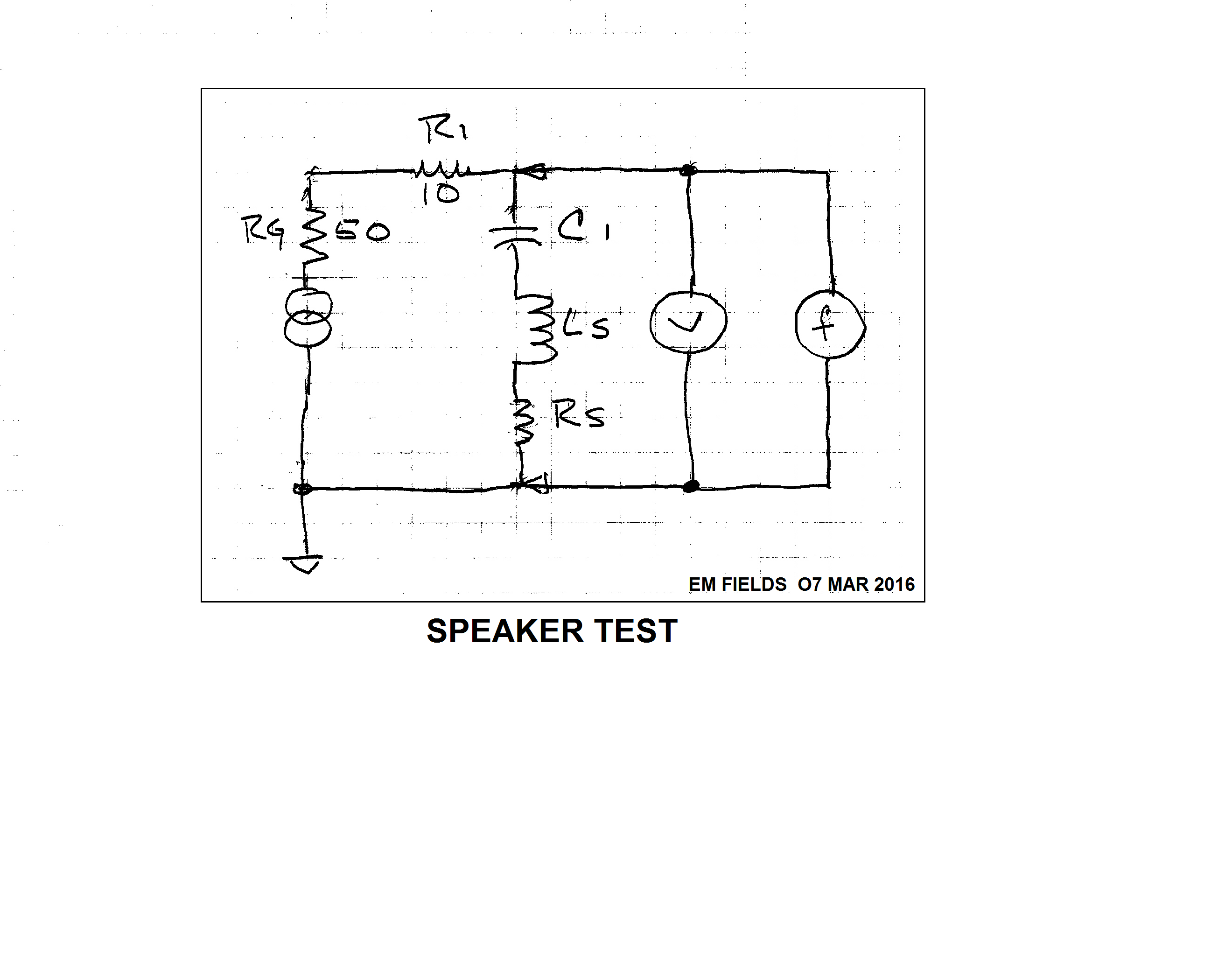
I tried it using this rig, where the generator's output impedance is 50 ohms, resistive, R1 is 10 ohms (just to increase the generator's output impedance a little), C1 is a capacitor decade box, Ls is the loudspeaker's inductance, Rs is the loudspeaker's resistance and "V" and "f" are an analog scope and a frequency counter, respectively.
enter image description here

To use it, I set C1 to 500 nF and adjusted the generator for a dip in the scope's response, recorded the frequency and capacitance of C1, then repeated the procedure for 100nF and 1\$ \mu F\$. After the arithmetic, here are my results:

  C1     f      Xc      L    
  nF    kHz    ohms    uH
 100   50.4     31     100
 500   20.6     15.5   120
1000   14.6     11     120

Now for the power...

In order to determine how much power is being dissipated by the voice coil, with a given voltage across it, we can write:

$$ P = \frac{E^2}{Z} $$

Where P is the power in watts, E is the RMS voltage across the coil, and Z is the impedance of the series RL comprising the coil.

In order to determine the impedance of the coil we can write: $$ Z = \sqrt (R^2 + X_L^2) $$

The measured resistance of the coil at DC was 8.1 ohms, and plugging that into the formula along with the coil's calculated reactance at 14.6kHz gives us:

$$ Z = \sqrt (8.1\Omega^2 + 11\Omega^2) \approx 13.7 \text{ ohms} $$

The loudspeaker I used to get the data is a Panasonic EAS6P22S which is rated for 500 milliwatts, so to find out what voltage we need to drive it to full power (at 14.6 kHz) we can rearrange:

$$ P = \frac{E^2}{Z} $$

to

$$ E = \sqrt PZ $$

and solve:

$$ E= \sqrt (0.5W \times 13.7\Omega) \approx 2.6VRMS $$

\$\endgroup\$

Your Answer

By clicking “Post Your Answer”, you agree to our terms of service and acknowledge you have read our privacy policy.

Not the answer you're looking for? Browse other questions tagged or ask your own question.