Given your instructor's remark, I suspect that you were actually told about "debouncing", which a very useful function. However, the circuit shown is a bad, bad example of how to do it.
Let's think about a switch making contact. Inside, you have two pieces of metal making contact, and on a timescale of milliseconds the two pieces can actually bounce, perhaps repeatedly, before settling down. If this happens the switch output will apparently show multiple activations where only one was intended. To combat this, a circuit like this can be used:

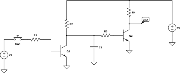
simulate this circuit – Schematic created using CircuitLab
You've noticed that it has the same general outline as your circuit, but a few more resistors.
Let's say that the switch is open, and gets briefly closed, then open, then closed for good (a single bounce). Current through R1 turns on Q1 and pulls the collector low. This also discharges C1. As a result Q2 is turned off and Vout goes high. When the switch bounces, Q1 is briefly turned off and its collector rises. However, the resistor charges up much more slowly than it discharges (for appropriate resistor values of R2 and R3), so Q2 never turns back on. As a result, the output Vout has been "debounced", and R2/R3/C1 can be selected for any desired bounce time to be ignored.
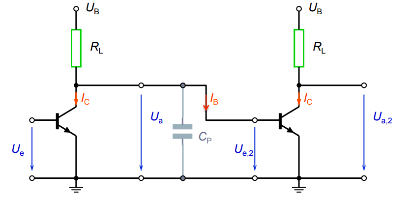
The original circuit is not very good, since the capacitor voltage swing is quite small, due to the clamping effect of the Q2 base-emitter junction.


