1
\$\begingroup\$

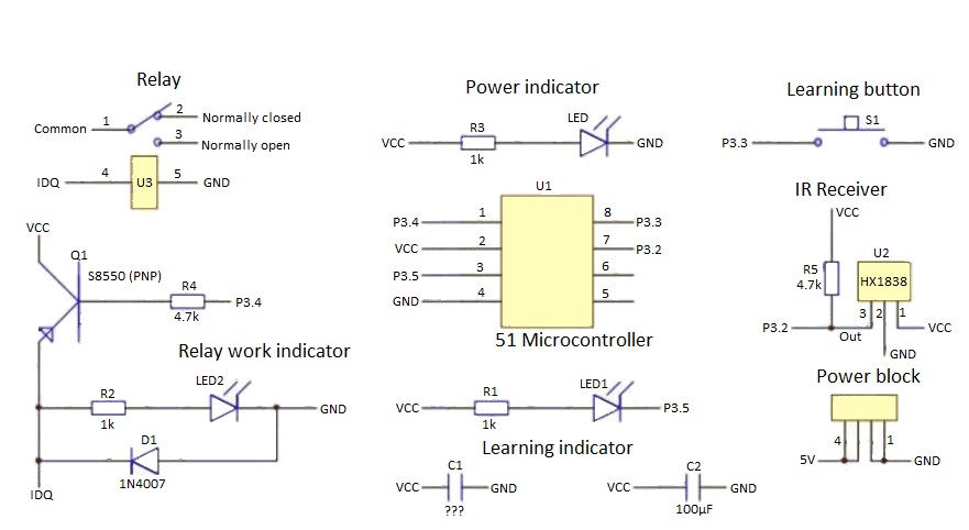
I have an IR Controlled Relay module (Schematic below). I have programmed it to work with an old Comcast remote (Silver with red select button). The problem I am having is the remote send the power signal multiple times per button press instead of just once. This causes the relay to switch rapidly and often end up in the same state as before you pressed the button.

So what I need to do is modify the circuit so that only the first signal gets through and the rest are ignored. I would assume that using a capacitor to smooth out the signal would be required, but what capacitance, where exactly should it go, and ceramic or electrolytic?

NOTE: This schematic was provided by the manufacturer in Chinese. I translated it but there is one existing capacitor (C1) that is a surface mount and I see no way to identify it.

IR Control Relay Module-English Schematic

What about using a 555 and this logic?

enter image description here

\$\endgroup\$

1 Answer 1

1
\$\begingroup\$

One solution to your problem here is going to be to change the software in that 8051 derivative microcontroller. Another solution is to select another IR remote that uses a different protocol and see if the embedded software in the MCU is smart enough to filter out repeats.

Virtually all IR remote controls will transmit their code repeatedly when a button is pressed. The typical rate is about 10 times per second. Some types of controls use a simple protocol where every one of the repeated transmissions are the same. Another type will send out the fully encoded transmission for the button press once and then send a shorter sequence than means repeat repeat. Then there are remotes that use Philips RC-5 protocol where there is a "toggle bit" in the protocol that changes state only when a new button press occurs. As long as the receiver sees the same toggle bit value received it knows that it is a repeated transmission.

If you are able to modify the MCU software by replacing the MCU with one that you can re-program then the easiest thing to do is to detect when the arriving transmissions are still repeating at the approximate 10 Hz rate and ignore anything that keeps coming till maybe there is no detection for say half a second.

\$\endgroup\$
4
  • \$\begingroup\$ Unfortunately replacing or reprogramming the MCU is not an option for several reasons. I don't have a scope, but I would assume the signal coming from the IR receiver is sending the signal as voltage pulses. If I dropped a cap across the signal pin and the ground pin to smooth out that pulse to a long drawn out single pulse, I am thinking that may work. I am not sure what size cap to try. Do you think that might work and what size cap should be used? \$\endgroup\$
    – Maverickz
    Commented Jan 31, 2017 at 6:27
  • \$\begingroup\$ Just adding some R/C low pass filtering at the output of the IR receiver is not going to work just on its own. If you did that the MCU would not be able to detect anything from the IR remote transmitter. I could envision a possibility of designing something where you added a circuit that detected when the MCU output first turns the relay on or off and uses that to trigger a timer chip and a flip flop. The output of the flip flop would disable the signal path from the IR receiver to the MCU through an AND gate. The timer would eventually timeout and clear the (continued) \$\endgroup\$ Commented Jan 31, 2017 at 6:55
  • \$\begingroup\$ (continued from above) flip flop to enable the IR path again. Such solution would not be perfect as it would not gracefully handle the case where the button on the IR remote was held down for longer than the timer period. Also please consider that design of such a thing may very well be pretty hard to get just right without an oscilloscope and would require some real circuit design experience. So in the end I think you are going to have to look at other alternatives than thinking about how to hack the IR relay module that you have in hand. Do try another type of IR remote control. \$\endgroup\$ Commented Jan 31, 2017 at 7:00
  • \$\begingroup\$ How about if I used a 555, an OR, and an XOR. (see new image added to original question for layout details) The 555 would be triggered by the output of the MCU (P3.4) when the relay was tripped. As long as the Timer out is high the signal from the IR receiver looks to be effectively blocked. I figure a 1000uF cap and a 4.5k ohm resistor should give about a 5 second blocking of the signal which should be more than enough. Any opinion or input on this possibility? \$\endgroup\$
    – Maverickz
    Commented Feb 1, 2017 at 7:08

Your Answer

By clicking “Post Your Answer”, you agree to our terms of service and acknowledge you have read our privacy policy.

Not the answer you're looking for? Browse other questions tagged or ask your own question.