0
\$\begingroup\$

I want to sense brightness via an OSRAM SFH3310 phototransistor by using an ADC (Vref 3.3V - teensy 3.1).

I understand that I need a voltage divider to get a good ADC reading. In the past I simply connected a potentiometer and tried out which resistance value maxed out the ADC value. The best value I figured was 120k.

schematic

simulate this circuit – Schematic created using CircuitLab

I would love to understand the datasheet more precisely, to have a more engineered approach :-)

enter image description here

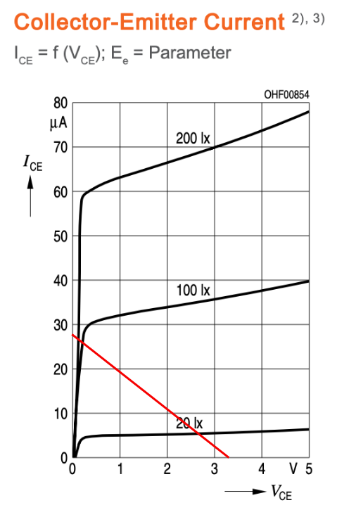
From this diagram, I would derrive, that at 3.3V at 20lux (almost dark), I would have a current flow of around 5uA. According to Ohms law, this would mean a resistance is R=3.3V/0,000005A= 660kOhm? In brightness I read 70uA, R=3.3/0,000070A=4.7kOhm. Do I use these values for R1 in the voltage divider.

I'm not sure if I got the right thinking here.

Thanks a lot for your help.

\$\endgroup\$

2 Answers 2

1
\$\begingroup\$

You can use a load line to better understand what is happening. A circuit like this will force the transistor voltage-current relationship to be on a straight line (a load-line). The Y intersection is 3.3V/120000 = 27.5 uA for your resistor choice. The X intersection is your Vcc. Note that the graph is showing the opto-transistor voltage (Vce), your ADC voltage is 3.3 - Vce.

Unless your circuit is more exotic, the resistor choice is a compromise. If the resistance is too high, then high light levels will be difficult to differentiate. If the resistance is too low, then low light levels will be difficult to differentiate.

Your resistance is on the high side, so as you can see in the graph, 100 lux and 200 lux will put out almost the same voltage. (this is not necessarily bad)

If you are looking for a light threshold, you would normally want that threshold to correspond to about half of Vcc. This part has a fairly wide variation from part-to-part, so it might be best to adjust with a pot.

If you are trying to measure the light level, you probably should use a different sensor and a more complicated circuit.

enter image description here

\$\endgroup\$
1
  • \$\begingroup\$ This won’t work unless you define CE pins in a circuit. \$\endgroup\$
    – D.A.S.
    Commented Jul 6, 2019 at 15:31
0
\$\begingroup\$

All you need is a resistor to define max Lux and and max voltage.

A better choice may be the AMS302(?) which has a log output up to 5 decades of Lux.

You must define your interface specs.

If ADC must be linear, you only get a small linear dynamic range before it saturated, then you might as well have a comparator or Schmitt Trigger for 100lux at Vdd/3 with Rc= 2V/uA +/- tolerance on uA for 3V-(Vce=1V)=2V the lower level of a Schmitt trigger.

But again define the functional and interface requirements or SPECs is a MUST HAVE for any design!!!

\$\endgroup\$
4
  • \$\begingroup\$ Thanks Sunnyskyguy, If I want to have a max of 200 lux and 3.3V as voltage at the ADC, how do I get these together? \$\endgroup\$
    – Chris
    Commented Jul 6, 2019 at 15:15
  • \$\begingroup\$ Ohms Law. Learn it \$\endgroup\$
    – D.A.S.
    Commented Jul 6, 2019 at 15:17
  • \$\begingroup\$ I know Ohms law and voltage dividers. I just want to understand if I can see the phototransistor as a resistor with the values I've mentioned in my post? Means 660kOhm in darkness and 4.7kOhm @200lux. That's all \$\endgroup\$
    – Chris
    Commented Jul 6, 2019 at 15:23
  • \$\begingroup\$ pad 1 is the emitter. Ground that and use R on the collector to define by Ohms Law otherwise there is no current to voltage gain. What are your interface specs??? \$\endgroup\$
    – D.A.S.
    Commented Jul 6, 2019 at 15:28

Your Answer

By clicking “Post Your Answer”, you agree to our terms of service and acknowledge you have read our privacy policy.

Not the answer you're looking for? Browse other questions tagged or ask your own question.