3
\$\begingroup\$

I recently ordered a PCB and on one component footprint I accidentally set the solder pad size to what should have been the hole size (diameter) for a thru-hole component.

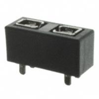
The difference is about 0.5mm / 20mil. The component is a fuse holder with two pins per terminal which I will use with a 10amp fuse (so roughly 5amps will be carried by each pin):

fuse holder

In order to do some testing on this board while I wait for a re-order, I am wondering about a temporary fix. Here are my questions:

  • Can I use a drill to increase the size of the holes?
  • Do I need to do anything to the hole after increasing the size in order to ensure a good connection?
\$\endgroup\$
3
  • \$\begingroup\$ The site's image hosting tool appears to be down. \$\endgroup\$
    – DerStrom8
    Commented Mar 14, 2017 at 20:48
  • 1
    \$\begingroup\$ The force applied to insert and remove a fuse will destroy a thin-wire solution. Change to solder-in fuses (pigtail type), or wire to an off-board fuseholder. Or, redesign the board. \$\endgroup\$
    – Whit3rd
    Commented Mar 14, 2017 at 22:21
  • \$\begingroup\$ @Whit3rd that's a good point about the force needed for the fuse... worthy of an answer. \$\endgroup\$
    – LShaver
    Commented Mar 15, 2017 at 17:31

2 Answers 2

3
\$\begingroup\$

If you the board is only two layers, and assuming you have clearance from other traces, you can drill out the plated-through holes. You'll have to make sure there is enough trace left to connect to, and you'll need to scrape the solder mask off of these traces.

This will also disconnect the top and bottom layers of your board in this location, so you may need to solder your fuse holder to both sides, or simply use a small piece of wire through the hole to connect them again.

If your board has internal layers then you probably shouldn't try. You may expose the inner layers and create shorts.


Upon reflection, I would be very hesitant to do this with 10A fuse holders. Solder isn't as conductive as copper. Perhaps you could expose the traces (remove the solder mask) and then solder appropriate wire from the trace to the fuse holder.

Or, for the easiest solution, do what @DerStrom8 suggested :)

\$\endgroup\$
2
  • 1
    \$\begingroup\$ The other issue with doing this for a fuse holder, as Whit3rd commented, is the force required for inserting/removing the fuse. In the end I decided just to forgo fuses on the board (so I soldered a jumper across the fuse holder) and use in-line fuses on the external wiring, until I re-order more boards. \$\endgroup\$
    – LShaver
    Commented Mar 15, 2017 at 17:33
  • \$\begingroup\$ @LShaver That sounds like a good solution. Thanks for coming back and letting us know :) \$\endgroup\$
    – bitsmack
    Commented Mar 15, 2017 at 17:55
3
\$\begingroup\$

Possibly, though it is probably not a very good idea. If you try to drill it by hand then you will drill out a significant portion of the pad and all of the barrel of the through-hole. Even if you are lucky enough to be able to solder to the remaining pads after drilling out the hole further, you will want to solder on both sides (top and bottom) of the board to 1) make all connections (mostly important if you have traces connecting to the through-hole on multiple layers), and 2) to provide a little more structural support (to prevent the pad from pulling off the board). Other problems with drilling out the holes could include cutting into nearby traces or ground/power planes and shorting them together. Your best bet would be to try to solder the components on small wire standoffs that can fit into the existing through-holes, or maybe try to use them as surface mount pads, or something of that sort. You may need to be clever with this one.

EDIT: Using small wire standoffs would probably not be a good idea in this case, as they themselves will behave as fuses, possibly before the actual fuse does!

\$\endgroup\$
3
  • \$\begingroup\$ Wow, we were thinking alike and typing at the same time :) \$\endgroup\$
    – bitsmack
    Commented Mar 14, 2017 at 20:56
  • \$\begingroup\$ We were indeed! I was just a few seconds too late XD I shouldn't have taken a break in the middle of typing my answer, I guess ;) lol \$\endgroup\$
    – DerStrom8
    Commented Mar 14, 2017 at 21:00
  • \$\begingroup\$ I think the consensus from both answers is that there aren't really any good options. As I mentioned on @bitsmack's answer, I ended up just soldering a jumper wire in place of a fuse, and will use external fuses temporarily. \$\endgroup\$
    – LShaver
    Commented Mar 15, 2017 at 17:34

Your Answer

By clicking “Post Your Answer”, you agree to our terms of service and acknowledge you have read our privacy policy.

Not the answer you're looking for? Browse other questions tagged or ask your own question.