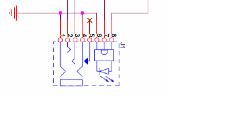
I'm very very very new for electronics design. I have a basic electronics knowledge but I know there 's many things I don't know in electronics symbol universe. I searched for reference circuit of CM103AH and I found it but I don't know what this jack is, Is it jack with LED ? I only know that 1 - 5 is a jack. Anyone can bring light to me what are 6, 7 and 8 ? or what is this type of jack called ?
-
\$\begingroup\$ Somewhere near this symbol should give you the part number of this component, then you can google for it. \$\endgroup\$– user3528438Commented Apr 4, 2017 at 16:00
-
\$\begingroup\$ Please link the full reference design and data sheet, and explain what the CM103AH is - it doesn't seem to be readily google-able. Usually a reference design will include a bill of materials that specifies the part number for each component. In the absence of other information I would guess this might be a TOSLINK jack. \$\endgroup\$– pericynthionCommented Apr 4, 2017 at 16:04
-
\$\begingroup\$ It's an illuminated barrel connector of some type. Or perhaps a jack/fibre-optic combination. \$\endgroup\$– Trevor_GCommented Apr 4, 2017 at 16:06
-
\$\begingroup\$ BTW.. that may not actually be a part, but rather a phantom part what is really a connector where you connect a cable that goes to the actual part(s). Or even a sub-assembly. \$\endgroup\$– Trevor_GCommented Apr 4, 2017 at 16:15
-
1\$\begingroup\$ I think it's a standard 3.5mm/fiber optic audio jack combination \$\endgroup\$– DerStrom8Commented Apr 4, 2017 at 16:35
2 Answers
It's probably a Mini-TOSLINK port which combines 3.5 mmm electrical stereo and optical S/PDIF / TOSLINK in one connector.
Pins 6, 7 and 8 are related to the laser diode of the TOSLINK output.
Wikipedia says:
Combined 3.5 mm jack and mini-TOSLINK sockets exist which can accept a 3.5 mm jack or a mini-TOSLINK plug; mini-TOSLINK plugs are made 0.5 mm longer than electrical jack plugs so that the latter are too short to touch and damage the LED of combined connectors. Many laptop computer and portable digital audio equipment models, such as the Google Chromecast Audio device[6][7] and Apple AirPort Express and iPod Hi-Fi, use these connectors that allow for the insertion of 3.5 mm electrical headphone output or microphone input or mini-TOSLINK digital output.
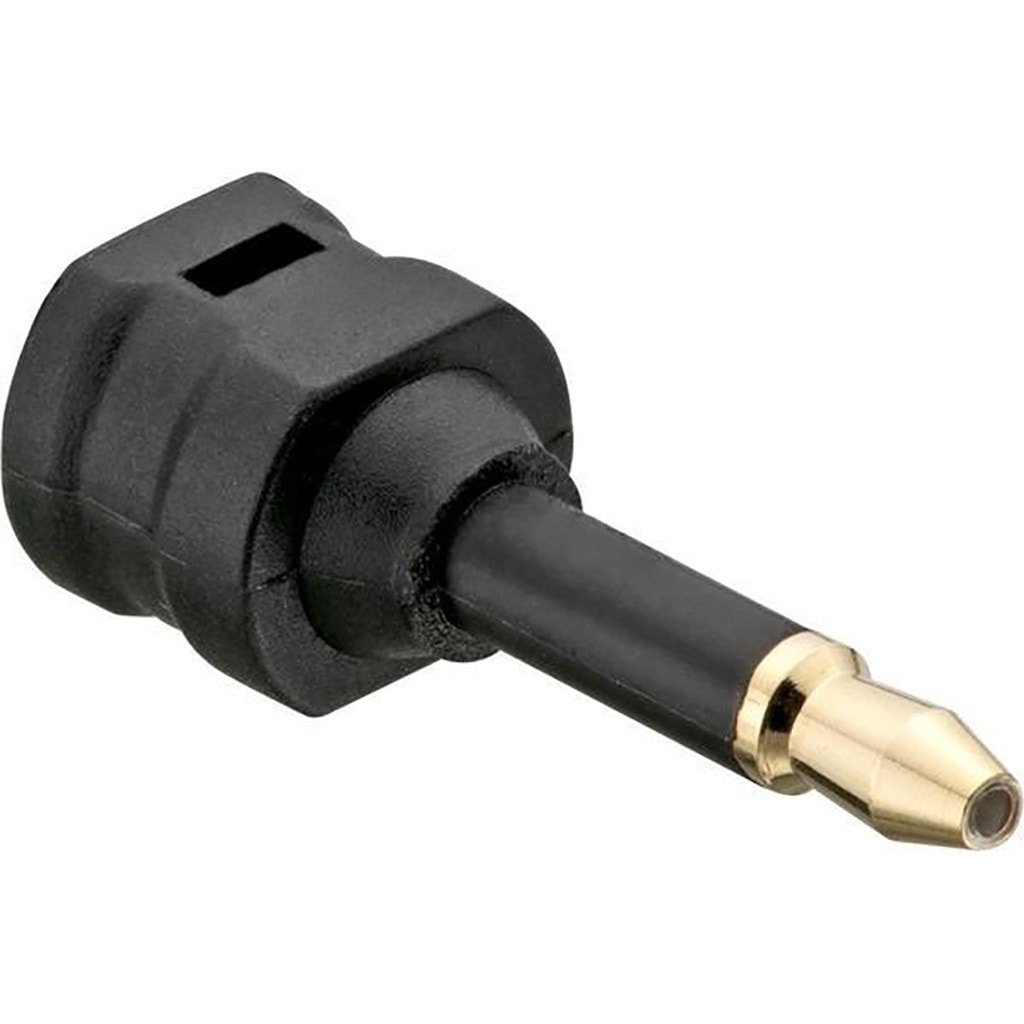
This is an adapter used to convert standard TOSLINK to Mini-TOSLINK. Note the typical 3.5mm jack form:
(Source: radioshack.com)
- The first part of the image is an AUX female connector (from 1 to 5).
- The second part is the bi color led (from 6 to 8).
My judgement would be
1 and 4 are the ground for AUX
2 and 3 are left and right channel for AUX
5 is unused
6 is ground for bi color led
7 is input for first color
8 is input for second color
The dotted line is the symbol for these parts to be coupled together, maybe encased alongside one another.
The similar circuit can be used to check if the connector is plugged in or not. If plugged in show green else show red color etc.
-
\$\begingroup\$ Why would they use that symbol for a bi-color LED? \$\endgroup\$ Commented Apr 4, 2017 at 18:20
-
\$\begingroup\$ I've seen many non standard drawings actually using the components as symbols. But now even I'm leaning towards the TOSLINK adapter. \$\endgroup\$ Commented Apr 4, 2017 at 19:58
-
1\$\begingroup\$ Why use a bi-colour LED to show whether a connector is plugged in when the connector is right next to it and it's obvious? What makes you even think it's a bi-colour LED? This isn't an answer, it's complete guesswork. \$\endgroup\$– FinbarrCommented Apr 4, 2017 at 21:24


