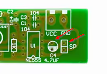
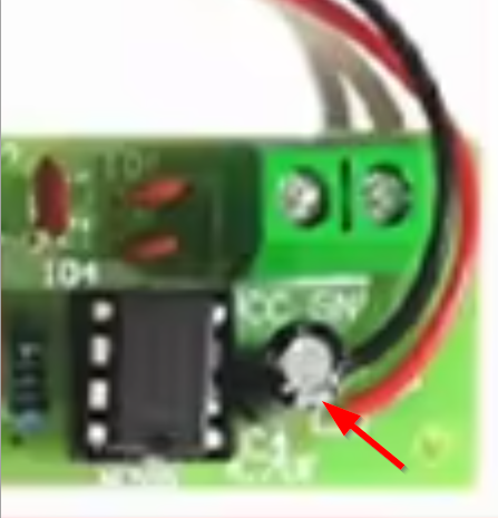
Important: It depends on the component type!
In case of capacitors then the marking on aluminium electrolyte capacitors specifically is for negative. Meaning that the marked side should be matched against the black stripe on the capacitor. In this case you very likely have an aluminium electrolyte.
Note however that in case of tantalum capacitors, the marking indicates the positive side! Tantalum caps don't usually come in can-shaped packages however, but in case of through-hole, blob-shaped packages.
In case of ceramic or film capacitors, they do not have polarity and should therefore (pedantically following IPC requirements) instead be soldered so that the component text can be read when holding the board as in your picture.
In case of diodes, the marking is always the negative (cathode).
In case of connectors, there are as many options as there are types of components.
And so on. Although, if the PCB was made by a sane designer (not necessarily the case) then the PCB markings in silk screen should follow the component markings, no matter the component.


