1
\$\begingroup\$

I've been playing with a couple servomotors i got from surplus of pick and place machines. So far, i've decoded their pinout and i'm working on reading the encoder, here comes the problem:

From what i observed, motor comes fitted with a 4096 cuadrature pulses per revolution +1 index pulse each revolution. Doing some testing in the Arduino IDE showed that spinning the motor a little faster and the encoder starts loosing steps...

I decided to migrate the code to AS7 and flush all the Arduino overhead, but the chip seems incapable of dealing with it. Correct me if i'm wrong about the following:

With 2048 cpr (just using the rising pulse of one cuadrature channel) and a rotational speed of 3000rpm, one revolution is complete in 0.02seconds.

Assuming the previous 20mS / 2048ppr we have one rising edge every 0.097mS -> 97uS give or take.

Is that time enought for executing the following ISR?:

#define F_CPU 16000000UL

#include <avr/io.h>
#include <avr/interrupt.h>
#include <util/delay.h>
#include <stdio.h>

volatile int count;

int main(void)
{

    DDRD  = (0<<PORTD2) | (0<<PORTD3)| (0<<PORTD4); 
    PORTD = (0<<PORTD2) | (0<<PORTD3)| (0<<PORTD4);  
    EICRA = (1 << ISC11) | (1 << ISC01);  // Configure interrupt trigger on rising edge of INT0  
    EIMSK = (1 << INT0); //ebable INT0 
    sei();

    while (1) 
    {

    }
}

ISR (INT0_vect){

    uint8_t i = ((PIND & 0b00010000)>>4);


        if (i == 1) {

            count = count +1;

            }else{

            count = count -1;
        }       

    EIFR = (1<<INTF0);
}

If not, how should i do it... Dedicated counter IC?

Thanks

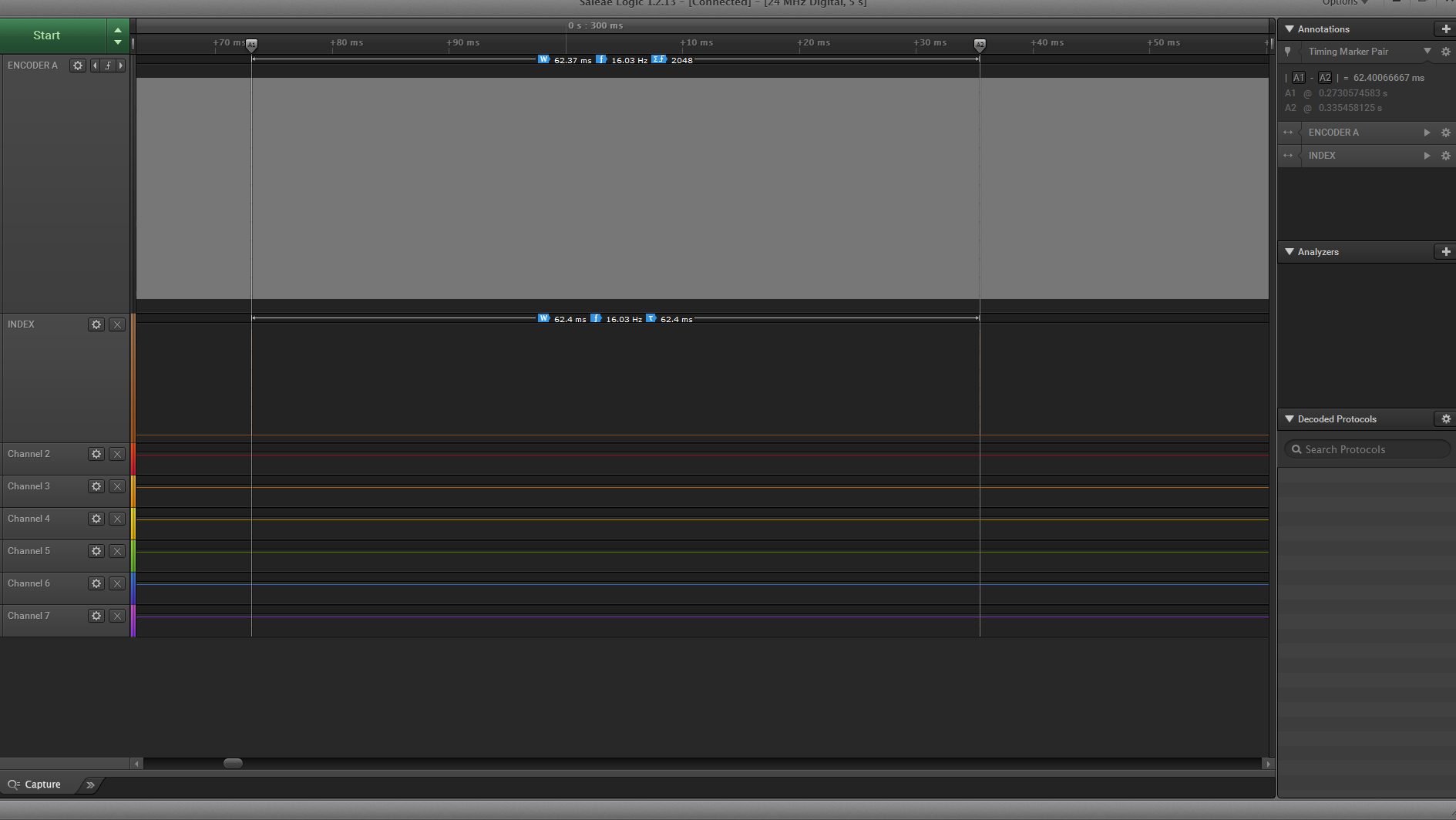
**Edit:**capture of the logic analyzer comparing one revolution (index) to encoder A

capture

\$\endgroup\$
7
  • \$\begingroup\$ You have not mentioned MCU frequency, but even for something like 1 MHz, it is still ~100 cycles, which has to be enough for ISR above. Don't you have any other (slower) ISR in your code or other long block with IRQs disabled? Is the electrical signal at pins OK (limit of the encoder, trace inductance/capacitance, pull-ups, ...)? \$\endgroup\$
    – Martin
    Commented May 16, 2017 at 16:05
  • \$\begingroup\$ But, actually, your math is off. 20 ms / 2048 is only 10 us, not 100 us. So, what frequency is your MCU running? \$\endgroup\$
    – Martin
    Commented May 16, 2017 at 16:10
  • \$\begingroup\$ Ignoring for now that time is measured in seconds, not Siemens, with non-optimising compiler, your ISR will likely come in at about 4+12+10+12+4 = 42 cycles. Give or take a couple as I'm guesstimating. With @Martin's correction, you need to be running at 4.2MHz to keep up, when doing nothing at all else. So that's minimum 12MHz realistically when not doing much or anything else.... so... \$\endgroup\$
    – Asmyldof
    Commented May 16, 2017 at 16:24
  • \$\begingroup\$ Oups, forgot to mention, right now i'm running on a standard Arduino Uno at 16MHz. @Martin, you're right, i'm sneaky posting from the office and forgot one 0! The code isn't doing anything else than performing the avobe ISR, let me post the full code. \$\endgroup\$
    – Aleix
    Commented May 16, 2017 at 16:42
  • \$\begingroup\$ @Martin, as seen in the scope, pulses look crisp and nice, don't think it's a signal integrity issue. \$\endgroup\$
    – Aleix
    Commented May 16, 2017 at 16:50

3 Answers 3

4
\$\begingroup\$

I have run your code through avr-gcc with -Os optimization (YMMV if you use different compiler, flags etc., but in could be good starting point) and disassembled result, here is it:

00000090 <__vector_1>:
 2  90: 1f 92           push    r1
 2  92: 0f 92           push    r0
 1  94: 0f b6           in  r0, 0x3f    ; 63
 2  96: 0f 92           push    r0
 1  98: 11 24           eor r1, r1
 2  9a: 8f 93           push    r24
 2  9c: 9f 93           push    r25
1 2 9e: 4c 9b           sbis    0x09, 4 ; 9
2 . a0: 06 c0           rjmp    .+12        ; 0xae <__vector_1+0x1e>
. 2 a2: 80 91 00 01     lds r24, 0x0100
. 2 a6: 90 91 01 01     lds r25, 0x0101
. 2 aa: 01 96           adiw    r24, 0x01   ; 1
. 2 ac: 05 c0           rjmp    .+10        ; 0xb8 <__vector_1+0x28>
2 . ae: 80 91 00 01     lds r24, 0x0100
2 . b2: 90 91 01 01     lds r25, 0x0101
2 . b6: 01 97           sbiw    r24, 0x01   ; 1
 2  b8: 90 93 01 01     sts 0x0101, r25
 2  bc: 80 93 00 01     sts 0x0100, r24
 1  c0: 81 e0           ldi r24, 0x01   ; 1
 1  c2: 8c bb           out 0x1c, r24   ; 28
 2  c4: 9f 91           pop r25
 2  c6: 8f 91           pop r24
 2  c8: 0f 90           pop r0
 1  ca: 0f be           out 0x3f, r0    ; 63
 2  cc: 0f 90           pop r0
 2  ce: 1f 90           pop r1
 4  d0: 18 95           reti

Numbers before instruction addresses is my addition to disassembler output, number of cycles for execution based on AVR Instruction Set Manual. If I am counting it correctly, it is 43 cycles in total + 5 cycles for interrupt response (+ about 3 cycles for pin change to propagate). The ISR code can be hand-optimized into much shorter if necessary. But it even so it is about 50 cycles, 3 us @ 16 MHz.

PIND is read 12 cycles after ISR start, about 20 cycles (1.25 us) after INT0 edge. Should be still OK.

You do not have much marginal, but it should work. OTOH any other ISR will probably "kill" it as ATmega does not have interrupt controller with priority handling. Btw. in the code you put here, there is no processing of count variable, so even for test it need to be more complicated. Are you sure, you are not doing anything affecting ISR latency there?

As an alternative solution -- if you can consider XMega for your project (assuming you want to use AVR), these have hardware support for encoder and you can drive counter by it without need for FW interaction.

\$\endgroup\$
2
  • \$\begingroup\$ I'm not going to pretend i fully comprehend the extent of your explanation, that's going to take me some time to read and google. There are no other ISRs, for debugging, the value counter was stored and printed in the main loop every 2 revolutions (1 revolution to sample (no interference from the uart print) and another to print (with it's possible missing counts due to the print). I'll definitively take a look at the xmega, i'm an industrial engineer, toyed a bit with Arduinos and i wanted to take this project as an opportunity to learn a bit more! \$\endgroup\$
    – Aleix
    Commented May 16, 2017 at 18:14
  • \$\begingroup\$ @Aleix, the note about other ISR was directed rather towards future, if you want to build on it, you will likely need to add some for functionality, you are targeting. About reading counter -- either you are doing it with ISR disabled (so potential timing issue if you are not careful), or you have race-condition reading multi-byte count variable while ISR can update it in the middle. If you see off-by-one error, then, maybe, it can be caused by latency of whole revolution detection in the code. \$\endgroup\$
    – Martin
    Commented May 16, 2017 at 18:25
1
\$\begingroup\$

There will be under 5 usec between rising edges because there are two sensors. That will leave zero CPU time to actually use the information for anything. Plus, most clean quadrature decoder schemes sample between all 4 edges, so that would leave only 2.5 uS between edges/samples.

You will probably be very tight on time to do 100% in firmware.

\$\endgroup\$
5
  • \$\begingroup\$ It's what i'm fearing, however spinning at around 1 revolution per second seems to affect the output the same way... \$\endgroup\$
    – Aleix
    Commented May 16, 2017 at 17:26
  • 1
    \$\begingroup\$ If it's not working at 1rps something else is wrong. \$\endgroup\$
    – Trevor_G
    Commented May 16, 2017 at 17:38
  • 2
    \$\begingroup\$ Indeed, by only looking at the rising edge of one of the channel and not requiring that a transition of the other intervene, the implementation becomes susceptible to multiply counting vibration over that edge. This is actually more likely to be seen at slow speeds or manual rotation than when running normally. \$\endgroup\$ Commented May 16, 2017 at 17:55
  • \$\begingroup\$ Take a look at the capture, i have the scope at work, unfortuately here i only have this small analyzer... @ChrisStratton, i understand it's far from ideal to do it this way, i was just testing the hardware. However, instead of loosing steps, should i be "gaining" steps? \$\endgroup\$
    – Aleix
    Commented May 16, 2017 at 18:19
  • \$\begingroup\$ You could be be multiply counting backwards jerks in the rotation. To an extent, it's not worth trying to debug implementation details of a flawed algorithm until you've fixed the algorithm itself. \$\endgroup\$ Commented May 16, 2017 at 18:31
0
\$\begingroup\$

10us is pretty fast even for faster clock rates.

You may want to consider feeding the clock pulse into a timer/counter and using that as a pre-scalar when driving the motor at speeds. Of course, transitioning from one mode to the other is tricky and needs to be done at slower speeds where you can guarantee a wide enough time window between pulses to preform the switch.

\$\endgroup\$
4
  • \$\begingroup\$ That's what i was seeing when googling around, that will very much annoy me, i have very little coding skills (almost nonexisting) and having to implement a switching function of that kind smells like frustration! \$\endgroup\$
    – Aleix
    Commented May 16, 2017 at 17:30
  • \$\begingroup\$ To my not huge knowledge what i tried to do there is: -Get the entirety of PIND -Mask it and shift the interesting bit to get either a one or 0 Could you please elaborate a bit more this: - Got it. \$\endgroup\$
    – Aleix
    Commented May 16, 2017 at 18:19
  • \$\begingroup\$ I'm using PD4, am I wrong doing shifting the resulting 00010000 four positions to the right? \$\endgroup\$
    – Aleix
    Commented May 16, 2017 at 18:25
  • \$\begingroup\$ @Aleix nvm.. my mistake.Apparently I misread >> \$\endgroup\$
    – Trevor_G
    Commented May 16, 2017 at 18:28

Your Answer

By clicking “Post Your Answer”, you agree to our terms of service and acknowledge you have read our privacy policy.

Not the answer you're looking for? Browse other questions tagged or ask your own question.