1
\$\begingroup\$

I was looking at this answer:
https://electronics.stackexchange.com/a/18479/76121
and I want to make sure that I understand...

I have a project that will be taking 120VAC current and turning it into 12VDC current using a Hi-Link HLK-PM12, which I need to switch a relay, and it will have a LD1117V33C to turn part of the 12VDC into 3.3VDC to run an ESP-01.

Now my question; the HLK-PM12 says that it's output is 12VDC, 3W.
According to the datasheet the LD1117 runs around 50C per Watt. I've been testing my circuit with a 9V battery, and the LD1117 gets a little warm, but not too bad. How exactly would I figure out how hot this thing might get with 12V 3W? If it's going to get up to 150C that's going to be a problem. Another problem is that this project is going to be outdoors, and so will be in a sealed project case, meaning while I can put a heat sink on, there won't be any air flow to help dissipate heat.

So how to I minimize heating with this?
Would a series of resisters between the HLK-PM12 and LD1117 drop the current enough to avoid a problem? If so, is this math correct?

I = P / C = 3W / 12V = .25A

And if so, what's the best way to figure out what resistors I'll need?

Another option would be to use a HLK-PM03 to turn 120VAC directly into 3.3VDC, and then I could avoid the whole LD1117 problem, but I don't know if that's necessary?

Please forgive me if I am misusing any terms. I'm something of a novice.

Edit: Plan B

Decided that the ESP8266-01 needs to have it's own power source, as there won't be enough current left over once the relay has been started.

So I came up with this schematic:
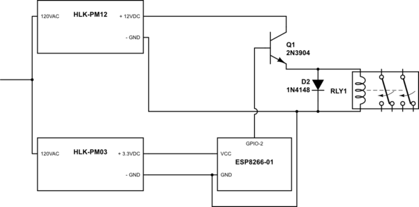
schematic

simulate this circuit – Schematic created using CircuitLab

I'm hoping this will put me more on the right track.

Maybe this should be a new question at this point, as I've basically found out that my original plan won't work.

\$\endgroup\$
1
  • \$\begingroup\$ you can put an LM7808 between the 12v and 3.3v LDO to share the thermal burden and slash the temp of the 117. you can use a LM317 if you can't easily find a fixed 8v regulator. \$\endgroup\$
    – dandavis
    Commented Jun 5, 2017 at 0:56

1 Answer 1

3
\$\begingroup\$

ESP-01 peak current draw is over 300mA. Your power supply can only deliver 250mA, and a linear regulator won't change this. Assuming you need 12V to power the relay, I would add a switching pre-regulator to drop the voltage down to 5V, then use the linear regulator to provide a stable 3.3V without getting hot.

This will draw less current from the power supply because the switching regulator 'transforms' high voltage at low current to lower voltage at higher current.

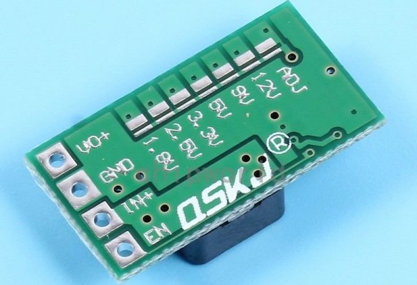
Small buck-mode regulator modules sell on eBay for about $1 each. Here's an example which has solder pads to select the output voltage:-

Mini DC-DC 12-24V To 5V Step Down Power Supply Module 3A Buck Converter

enter image description here

Another option might be to use a 5V 3W power supply and 5V relay.

\$\endgroup\$
12
  • \$\begingroup\$ A 1000u caps will eliminate any wifi current spikes; keeping it at about 80ma. a 470u cap will keep the spikes under 200ma, within the limit of the regulator. \$\endgroup\$
    – dandavis
    Commented Jun 5, 2017 at 0:53
  • \$\begingroup\$ Good input. The relay is 120VAC 30A and rated for a 1HP motor, and so it is pretty big. I couldn't find a relay that could handle that kind of load with a smaller switching voltage. So if 300mA is the maximum draw... I'm hoping it'll be less than that. All I need is for the wifi to work, and for it to be able to send a small current to a transistor to turn on the 12V current to the relay. I really am wondering if it would be better to use the HLK-PM03, which has an output of 3.3VDC 3W, which is a lot more amps than I need, but IIRC if the ESP01 doesn't need the amps it won't draw them... \$\endgroup\$
    – AndyD273
    Commented Jun 5, 2017 at 2:15
  • \$\begingroup\$ @dandavis Sorry, I'm not really sure how that would work? I'm still learning how to use caps effectively. \$\endgroup\$
    – AndyD273
    Commented Jun 5, 2017 at 2:17
  • \$\begingroup\$ you just connect the cap in parallel with Vin and Gnd. see this video for info \$\endgroup\$
    – dandavis
    Commented Jun 5, 2017 at 2:31
  • \$\begingroup\$ Typical 12V coil current for a 30A relay is 80~150mA, so you have 150-220mA left to power the ESP-01. With an RC filter you may get away with the linear regulator, but it's not good engineering. If the resistor is large enough to drop sufficient voltage during receive then regulator input voltage will be critically dependent on current draw, and the transmit duty cycle will have to be kept very low. \$\endgroup\$ Commented Jun 5, 2017 at 4:25

Your Answer

By clicking “Post Your Answer”, you agree to our terms of service and acknowledge you have read our privacy policy.

Not the answer you're looking for? Browse other questions tagged or ask your own question.