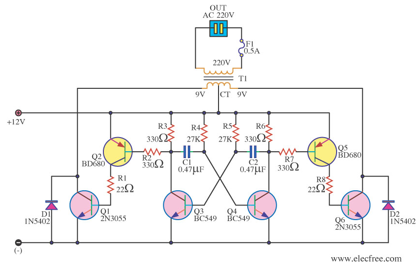
This is a very beginner's question - I apologize if this is something completely trivial but I am stuck trying to understand the exact functioning of the circuit below.
The circuit below is supposed to be a simple square-wave power inverter circuit and I am puzzled by: (1) the purpose of several elements, (2) the absence of some (what I think are) important elements.
More specifically:
What is the purpose of D1 and D2 diodes? This looks like some kind of a flyback diode application but I don't see how it helps with flyback for the coil: what would happen when Q6 is suddenly shutdown? Wouldn't the induced EMF from T1 just fry transistor Q6?
What is the purpose of Q2 and Q5 transistors? Couldn't I just connect the multivibrator outputs directly to Q1 and Q6? Is it done to increase the base-emitter currents in Q1 and Q6 respectively because of some kind of output power requirements? If it is only about power, why not just use MOSFETs for Q1 and Q6 instead of BJT?
It seems that there is no resistors in the path from +12V to coil to ground. Wouldn't this path become a short-circuit if there is no load connected to the 220V side of the transformer (and thus, no back EMF)?
The circuit is taken from here: https://archive.is/0yRJc

