4
\$\begingroup\$

enter image description here

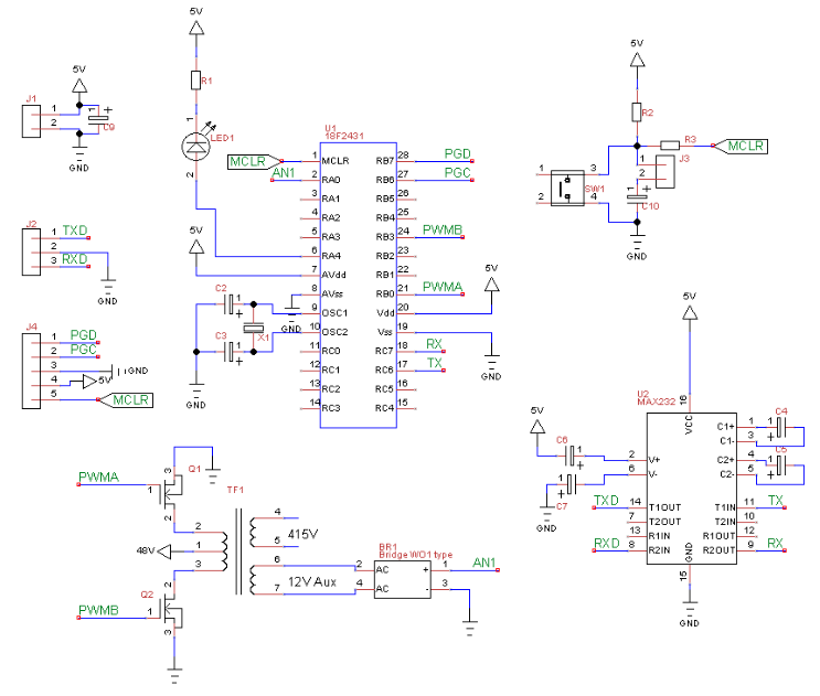
I would like to have an idea for a square wave inverter I am making.It would be a 48V to 415V in the final product, but initially I am trying it with a 24V to 207V with the same transformer.

I am implementing this with a PIC uC which will generate the 50Hz square wave,which will be used to switch the MOSFETs of a center tapped transformer in the push pull mode.

My query is how to get the feedback from the output to make a closed loop system.I am planning to wind an auxiliary winding for the feedback and assume the aux. winding will replicate the load winding.

The specific question is: Would it work if I calculate the RMS value of the output and then vary the input PWM to get the required RMS at the feedback winding?

Or would there be any simpler way to do this ?

\$\endgroup\$
8
  • \$\begingroup\$ A schematic would help visualize what you are describing. \$\endgroup\$ Commented Dec 4, 2012 at 13:07
  • \$\begingroup\$ Why can't you take your feedback from the primary side? \$\endgroup\$
    – Dave Tweed
    Commented Dec 4, 2012 at 13:29
  • \$\begingroup\$ sensing primary, secondary and spare coil for voltage are 3 methods used. What power levels do you anticipate and minimum load? \$\endgroup\$
    – D.A.S.
    Commented Dec 4, 2012 at 16:34
  • \$\begingroup\$ I have put up a rough draft of my schematic.It is only for conceptual verification from the forum members.I have not done any research on the the MOSFET driver circuits/snubber circuits.I am planning to use the 18F2431 to get a 50Hz PWM directly in a push pull mode. \$\endgroup\$
    – EmbSysDev
    Commented Dec 4, 2012 at 17:08
  • \$\begingroup\$ The power level in the final application would be a 5HP motor,which would be driven by a VFD.Since the VFD would synthesize the 3phase (8Hz slow speed for 60 seconds) for the motor, supplying it with a 415V single phase should work IMO.The minimum load would be very less maybe about 10W(electronic circuits and 4 relays) before the VFD is powered up by this inverter. \$\endgroup\$
    – EmbSysDev
    Commented Dec 4, 2012 at 17:21

2 Answers 2

1
\$\begingroup\$

Yes, at this input voltage a center tapped primary with low side switches on the ends seems like the way to go. For feedback, I'd look at opto-isolators first. Put something on the output side that can detect whether the voltage is above or below the regulation threshold and drive the opto accordingly. On the primary side, a simple control method is to simply stop the oscillations when the opto signal indicates the output is high. If you can live with some ripple, this should be effective, simple, and efficient.

\$\endgroup\$
2
  • \$\begingroup\$ Olin,thanks for replying.You mean I could just measure the peak voltages and use that,instead of computing the RMS value for feedback purposes? \$\endgroup\$
    – EmbSysDev
    Commented Dec 4, 2012 at 17:32
  • \$\begingroup\$ @embs: First, you said this was a square wave inverter, so peak and RMS are the same thing. Second, you can measure whatever you want and control the opto-isolator accordingly. The primary side will regulate to that threshold, however it is decided on the secondary side. \$\endgroup\$ Commented Dec 4, 2012 at 23:15
0
\$\begingroup\$

It isn't at all clear why you need feedback in this application. (For one thing, you haven't said what parameter you want to feed back — everyone seems to be assuming it's voltage.)

Unless your transformer has really poor coupling, its output voltage will be directly proportional to its input voltage. If it has the correct turns ratio to convert from 48V to 415V, why do you think the ouput voltage would be anything different?

The VFD probably does not require really tight regulation of its input voltage anyway; it's designed to be powered from mains, right? And it's going to be directly controlling the voltage/current in the motor. But if you do need to make adjustments, I think it would be easier to measure and/or regulate the 48V DC bus upstream of the transformer driver.

A 4kW transformer @ 50 Hz is going to be enormous. (Well, maybe not as big as the motor :-) If you really need isolation, it would probably be better to use a much higher switching frequency. If you don't really need isolation, a multiphase non-isolated DC-DC converter will probably end up being much more efficient. (There's a good chance the VFD will be perfectly happy with DC input.) Remember, you're going to be switching upwards of 80A on the primary side.

\$\endgroup\$
1
  • \$\begingroup\$ @ Dave,I have a locally made product available for the same purpose.The transformer is 15cmx13cmx9cm.Runs on a 72V battery,I saw another which runs on a 48V battery,with similar dimensions.As mentioned above,the equipment has to run for 60seconds,so its not a continuous duty cycle.Also motor would be running at 8Hz,so kW would be lesser ? kW = k.N.T.The PWM duty cycle changes depending on the load,maybe to conserve battery.The only feedback is the output voltage fully rectified and given to the PIC pin.My guess is duty cycle is increased if the output voltage droops under load. \$\endgroup\$
    – EmbSysDev
    Commented Dec 5, 2012 at 8:52

Your Answer

By clicking “Post Your Answer”, you agree to our terms of service and acknowledge you have read our privacy policy.

Not the answer you're looking for? Browse other questions tagged or ask your own question.