10
\$\begingroup\$

I'd like to ask a quite specific question regarding the USB power management.

First of all, I will outline the design of my device. It is a symmetric signal line driver with a builtin audio codec for my DIY speaker system. The device is internally split into two mostly independent blocks: the very line driver with a controlling MCU and the audio codec (TI's PCM2706). Both need USB data connectivity (via an FT232R for the driver block) and the whole device should be bus-powered. The two blocks will be linked together by an USB hub chip, yielding a single uplink USB connection to the PC. I expect the consumption of the driver stage to be something between 100 and 200 mA (definitely more than one load unit).

Here comes the problem: According to the USB specification, a bus-powered hub can provide only one unit per downstream port while drawing max 5 units from the upstream. I'd like to know, what would the hub do if I requested two units via the FT232 for the driver stage. The 5-unit upstream limit will not be reached (1 unit for the hub, 1 unit for the codec and two for the driver), so the computer should be physically able to supply that current.

For the hub chip, I've been checking out http://www.ti.com/lit/ds/symlink/tusb2036.pdf. There is an option of "ganged" powering mode, would this be any help? Or would the chip just refuse to grant two units to the driver? And in this case, is there any dirty workaround?

I am aware of the requirement that high power devices are also required to draw max 100 mA during enumeration; this is not a problem as the FT232 is able to turn the driver on just after the enumeration. The hub will turn the stages on independently as well.

Hope I stated my problem clear enough and thanks for your time in advance :)

UPDATE:

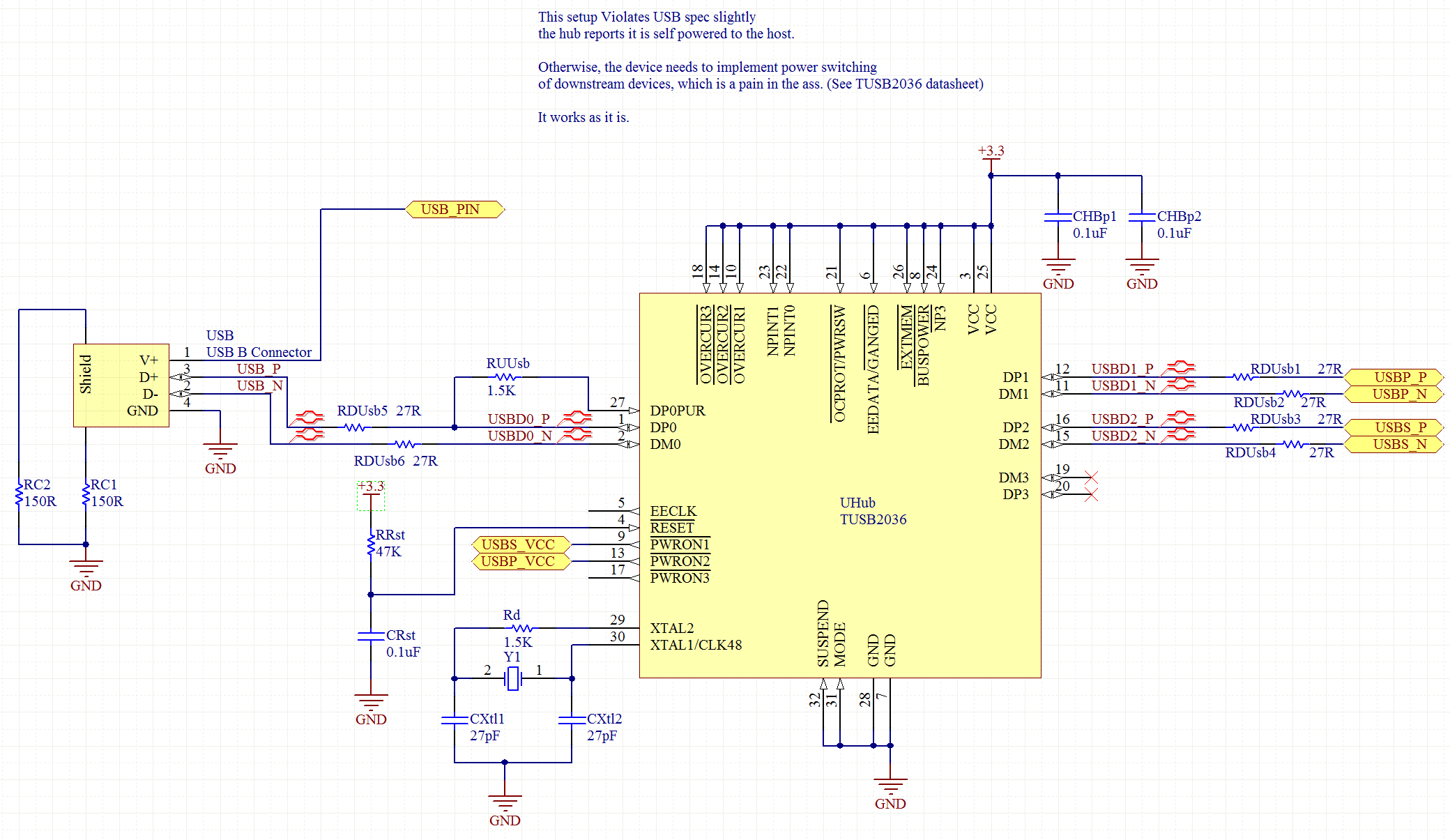
I did some more research on the TUSB2036 chip. The overcurrent protection can be turned off by the /OCPROT pin. The hub then reports to the root controller that it is not able to detect overcurrent. There is a warning in the datasheet, that OC protection is required by USB 2.0 specification - this does not matter for me, I only need 1.1 Full-speed. The PC's root hub should then IMO supply 500 mAmps to the whole device. Thus, I could set the driver's FT232 to require 100 mA only and the hub would never know if I would have exceeded the limit (respecting the 500 mA from the PC of course). Can someone tell if this could work?

\$\endgroup\$

3 Answers 3

3
\$\begingroup\$

My understanding of the your design is that the entire device is on a single PCB, is within a single enclosure, and is connected to the host by a single USB cable. You've integrated a hub onto the PCB to allow both the devices to communicate with the PC. The following answer will hinge on these assumptions, if it's made of several separate devices connected by disconnectable cables then that changes things.

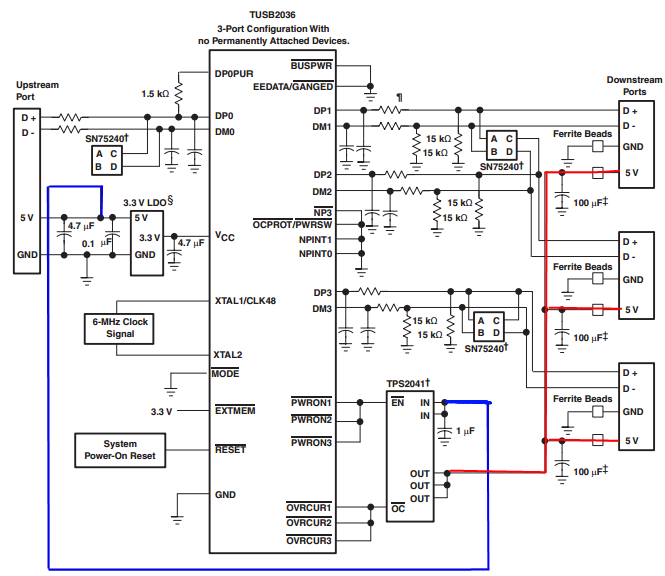
In this case, I suggest that you simply configure the hub to enumerate as a high-power device, and share the resulting 500 mA among the whole board. Interestingly enough, TI's ganged-port sample schematic shows the devices all connected together, even when using their power management IC:

enter image description here

The incoming 5V power supply line (highlighted in blue, as it's one of two nets that we're interested in on this complicated schematic) is connected to a TPS2041 power management IC (a generous description, it's really just a FET that shuts down when it detects 500mA of current being passed). However, each of the inputs are shorted together, and each of the outputs are shorted together as well, and then distributed to each of the downstream ports (the net shown in red).

Basically, they're doing overcurrent protection for all of the downstream sections in a single IC. They have no way of detecting whether they have three low-power (100mA) units, a single high-power unit, or two low-power units and one 300 mA unit. All these options are acceptable based on this reference design. You wrote:

According to the USB specification, a bus-powered hub can provide only one unit per downstream port while drawing max 5 units...

but, to directly answer your question, this design from Texas Instruments (a USB group member and major implementor) shows that you only have to guarantee that the total current is less than 5 units.


To solve your problem, the rules state (taken from the excellent USB in a nutshell document):

High power bus powered functions will draw all its power from the bus and cannot draw more than one unit load until it has been configured, after which it can then drain 5 unit loads (500 mA Max) provided it asked for this in its descriptor.

If you can guarantee that your driver stage will not begin drawing current until the device has been configured (which might be as simple as a timed delay in the host controller), you can simply wire everything together. Because your entire circuit is on a single PCB and has no user-accessible downstream ports, you can probably also leave out the TPS2041 and simply design the system to not require more than 500 mA of current in any state.

Another benefit of enumerating as a high-power device is improved input voltage specifications. When you have enumerated as a low-power device, the host is only required to produce 4.40 V at the upstream port (which will be lower at your device due to the resistance of the cable). When you have enumerated as a high-power device, the specification guarantees that you'll get 4.75 V, which is more likely to be within the operating range of any 5V components you may be using.

\$\endgroup\$
2
  • \$\begingroup\$ Thanks for an excellent answer. But how do I configure the hub that way? Do I need the external EEPROM or do I just tie the /GANGED pin to ground (and the other config pins according to the schematic you have sent)? \$\endgroup\$
    – Ladislav
    Commented May 8, 2012 at 8:23
  • 1
    \$\begingroup\$ You'd need to tie !GANGED to ground and !EXTMEM to 3.3V. However, the external EEPROM might be nice: Otherwise your device will show up as 'generic USB hub' on the PC. Alternatively, you could probably emulate an EEPROM with your onboard microcontroller (configure one of the I2C interfaces to act as a slave). Then you could report it as a 'Speaker system driver and codec controller' or something like that. \$\endgroup\$ Commented May 8, 2012 at 13:01
5
\$\begingroup\$

I have designed a board around that hub.

In my application, it was allowing access to a FT232 and a FT245.

If everything is on your own PCB, I would recommended you just completely ignore the entire overcurrent protection systems entirely. After all, if something on your PCB fails, the whole thing will need work, so making the device able to handle a partial failure is kind of a moot point.

In my situation, I strapped the TUSB to request the full 500 ma and disable the overcurrent protection, and just ran everything straight from the USB 5.0v. I accomplished this by forcing the hub to report as self-powered to the upstream host.

I have made a couple of the boards, without any real problems, so it seems a perfectly workable strategy. It's also been used with several different computers, so I'd feel pretty confident using it as-is.

Of course, if this is for a production device, rather then a personal project, or a test-harness (which is what it is in my case), it's a whole different problem.

enter image description here

(See the note on the schematic)


For what it's worth, you can often pretty horribly abuse most modern USB ports without too much trouble. A lot of them can supply far more power then the 500ma they are rated for, without too much trouble.
Also, most of them (all I have tested, barring some laptops) will happily supply the full 500ma without a device having to enumerate at all.

However, this varies from motherboard to motherboard, depending on how the USB host is designed. Your mileage may vary.

\$\endgroup\$
3
  • \$\begingroup\$ Yes, I've been thinking about that, but as you have said, this varies from MB to MB. The device will not be produced in thousands, but I need it to be as interoperable as it can be, so it would "Just work" on any computer. Thanks anyway, practical observations are just as valuable :). \$\endgroup\$
    – Ladislav
    Commented May 8, 2012 at 8:40
  • \$\begingroup\$ @Ladislav - I don't think there is anyway to avoid needing the ability to power-switch the downstream devices without violating the USB spec at least somewhat. \$\endgroup\$ Commented May 8, 2012 at 9:07
  • \$\begingroup\$ It's worth noting that if you strap the device to report as bus-powered, and just don't bother with the power-switching, it may work anyways. It could be worth testing. Alternatively, look for a USB-1.1 only hub IC. \$\endgroup\$ Commented May 8, 2012 at 9:09
1
\$\begingroup\$

Might be a bit dirty: the TUSB2036 allows for downstream port selection (p3 NPINT1-0 set to 10). Then connect your device to two (physical) ports so you can draw 2 units in parallel.

\$\endgroup\$

Your Answer

By clicking “Post Your Answer”, you agree to our terms of service and acknowledge you have read our privacy policy.

Not the answer you're looking for? Browse other questions tagged or ask your own question.