1
\$\begingroup\$

I have a 3v motor driven by a MOSFET that gets its input off an inverter circuit that comes off the output of a 555: Schematic
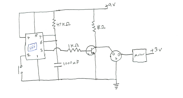
The idea is that when you press the button, it waits for about 20 seconds and then starts the motor. (It's for a rotating banner that goes under a drone, I need it to start spinning after the drone lifts off from the ground and not before!)

So it seems to work if I put an LED instead of the motor, but with a motor it makes a mess and becomes flaky. Sometimes the motor turns on, sometimes it doesn't, sometimes it runs for a few seconds and then turns off.

Motor is supposed to run on 3v, but I think it's not getting the full 3 volts. It's hard to measure as the voltage seems to change when I put the voltmeter on! When I replace it with an LED it seems dimmer than it would be if I hooked it up to straight 3v.

(The "GDS" circle thing is an IRFZ34N N-Type Power MOSFET, sorry I didn't know how to draw it.)

I tried replacing the 9v with 3v and 16v, still doesn't really work. Also tried replacing the 1k resisters with 100, they just got really hot.

Any ideas what I might be doing wrong and how I can get this to work? (Thanks for your patience, I'm a bit of a noob)

\$\endgroup\$
17
  • 1
    \$\begingroup\$ nMOS symbol is a similar symbol to a transistor, but it's more of a square shaped looking switch symbol (hard to explain but you can look it up on Google). \$\endgroup\$
    – user103380
    Commented Jul 2, 2017 at 3:46
  • 1
    \$\begingroup\$ You should have a flyback diode across the motor to protect the switch. \$\endgroup\$
    – user133493
    Commented Jul 2, 2017 at 4:46
  • 1
    \$\begingroup\$ "simply attaching the motor to the 3v power, resets the timer on the 555" Ahhh. That is what is going on. That may be hard to debug with a DVM. A bit more complicated to explain i a comment. You probably need to isolate the supply (and RC) from the motor and add parallel electrolytic and ceramic capacitor. The noise from the motor is likely tripping the 555. Also you may need to make the input to pin 2 less noise sensitive. \$\endgroup\$ Commented Jul 2, 2017 at 5:20
  • 1
    \$\begingroup\$ Other possibility is pin 2. When switch is off, there is nothing to pull that input solid high. I recommend a pull-up on that line (10K?). Could go lower to make more noise resistant \$\endgroup\$ Commented Jul 2, 2017 at 6:01
  • 1
    \$\begingroup\$ As well as cap for the motor feed (you mention 1000 uF) add a small series resistor in the feed between the cap and the motor that drops say 0.25V. (eg if motor current = 100 mA then R = V/I = 0.25/0.1 =~~ 2.5 Ohms. The R & C form a filter which helps isolate the motor noise. \$\endgroup\$
    – Russell McMahon
    Commented Jul 2, 2017 at 7:38

1 Answer 1

2
\$\begingroup\$

I bet you will learn a lot more if you figure it out yourself.

So, rather than telling you the answer, I am going to help you to get the answer yourself.

First break the problem/circuit into parts and check each part against how you think it should work.

I recommend:

  1. 555 and RC
  2. BJT
  3. FET
  4. Motor

For each part, consider what is required for each state. Start at the Motor and work backwards and check each with a DVM until something doesn't respond as you expect it would.

Ex: For the FET

Input(G)     Output(D)   Result   
0V           Off (3V)    Motor Not Running   
9V           On (0V)     Motor Running   
\$\endgroup\$
7
  • \$\begingroup\$ Thanks for your answer. Measuring voltages seems to change the state of the system though. Is this normal? Is there a way around this? \$\endgroup\$ Commented Jul 2, 2017 at 4:06
  • 1
    \$\begingroup\$ The DVM will introduce an impedance; but, it should be very high compared to what you are measuring but if a transistor is off, the impedance could be very high. Mostly force the inputs and measure the outputs. \$\endgroup\$ Commented Jul 2, 2017 at 4:09
  • \$\begingroup\$ I don't know what impedance means, but I'll look it up thanks. :) \$\endgroup\$ Commented Jul 2, 2017 at 4:36
  • \$\begingroup\$ So far I've figured out that attaching the motor seems to reset the transistors and restart the timer for some reason. Voltage is perfectly fine across everything until I attach the motor; seems to drain power for some reason \$\endgroup\$ Commented Jul 2, 2017 at 4:37
  • \$\begingroup\$ To debug this you really need to disconnect the 555 and work on that once you get the rest of the circuit working. \$\endgroup\$ Commented Jul 2, 2017 at 4:59

Your Answer

By clicking “Post Your Answer”, you agree to our terms of service and acknowledge you have read our privacy policy.

Not the answer you're looking for? Browse other questions tagged or ask your own question.