4
\$\begingroup\$

With regards to "catching" very high voltage transients on a DC power supply, is it possible to use a small, high voltage capacitor with a current limiting resistor to catch the transient in order to protect a much lower voltage, larger capacitor in parallel? Or will the transient destroy the lower voltage capacitor regardless? I assume that the high voltage capacitor and current-limiting resistor will have to be sized appropriately to be able to absorb the total energy of the transient.

Example circuit:
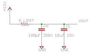
parallel capacitors

\$\endgroup\$
4
  • \$\begingroup\$ I've done this while repairing Switched Mode Power Supplies, indeed to protect the elco for spikes. Not sure about dimensioning though. \$\endgroup\$
    – jippie
    Commented May 11, 2012 at 18:58
  • \$\begingroup\$ I'd increase the Ch a bit to 47n or 100nF. You can check the effect with an oscilloscope. \$\endgroup\$
    – jippie
    Commented May 11, 2012 at 20:54
  • \$\begingroup\$ @jippie - "elco" is Dutch (and German too, I think). Not everybody here will understand it. \$\endgroup\$
    – stevenvh
    Commented May 12, 2012 at 6:07
  • \$\begingroup\$ Oh, never realized that, I was my 'world domination'-mode again ;o) - But you are right, I meant to say 'electrolytic capacitor' \$\endgroup\$
    – jippie
    Commented May 12, 2012 at 10:01

2 Answers 2

2
\$\begingroup\$

It's not clear how exactly you intend to connect the two capacitors. If they are in parallel, then they will see the same voltage, which then needs to be safe for the low voltage capacitor. If you are filtering the spike first thru a resistor and the high voltage capacitor, then another resistor to the low voltage capacitor, it may work depending on the time constants, the max spike voltage, and the total spike voltage-time integral.

Unless you are very sure about the exact characteristics of the spikes, this is probably a bad idea. How about clamping with a zener or transzorb or something instead?

\$\endgroup\$
2
  • \$\begingroup\$ I'm trying to design a very low cost, very simple power supply around a LM2931 for a prototype I'm working on that will be in an automotive environment. The LM2931 includes load dump protection and (apparently) a good deal of transient immunity, so I believe I can skip the TVS. It appears that I may be stuck with a larger, more expensive capacitor than I want. \$\endgroup\$ Commented May 11, 2012 at 19:16
  • 1
    \$\begingroup\$ MOVs are cheap, @QuestionMan. \$\endgroup\$
    – tyblu
    Commented May 11, 2012 at 20:46
1
\$\begingroup\$

In the circuit you drew, CH does approximately nothing to protect CL from over-voltage.

The limiting resistor does help to reduce the amplitude of a short spike seen by CH. This is because to raise the voltage on CH, a current has to flow in to CH. When this current is flowing, R_Limit will have a voltage drop according to Ohm's law, so capacitor CH will not see the full voltage applied at the +12V node.

However, if the "spike" lasts long enough, eventually CH will charge up, and current will no longer need to flow through R_Limit, putting CH above its voltage limit.

The only contribution of CL is to raise the capacitance to be charged from 10 uF to 10.0001 uF, which will reduce the voltage at VOUT during the transient by a miniscule amount.

\$\endgroup\$
4
  • \$\begingroup\$ I was afraid this was going to be the answer. \$\endgroup\$ Commented May 11, 2012 at 19:44
  • \$\begingroup\$ It is true if you neglect the non-ideal characteristics of the elco. Elco's have a bad performance for high frequencies (spikes) and very often a small cap will sufficiently filter these to increase elco life time. \$\endgroup\$
    – jippie
    Commented May 11, 2012 at 20:54
  • \$\begingroup\$ @jippie, You're point is valid; but also note that OP's drawing shows a non-polarized capacitor, not an electrolytic; on the other hand, 15 V doesn't seem to be an available WV spec for ceramics, so its not clear what OP is actually using. \$\endgroup\$
    – The Photon
    Commented May 11, 2012 at 21:36
  • \$\begingroup\$ Didn't notice the symbol to be honest, I just concluded it from the largish capacity with the lowish voltage. True it was an assumption. \$\endgroup\$
    – jippie
    Commented May 11, 2012 at 21:44

Your Answer

By clicking “Post Your Answer”, you agree to our terms of service and acknowledge you have read our privacy policy.

Not the answer you're looking for? Browse other questions tagged or ask your own question.