0
\$\begingroup\$

This is very similar to how common mode chokes work but can we implement this by using transistors?

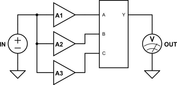
Lets assume we have a signal 's' we are trying to amplify.We feed this signal into some linear amplifiers a1, a2 ,a3 . These amplifiers are practical and not ideal and hence add noise to their output signal. Although these are practical conditions but lets assume for the sake of this concept that there is no phase shift in the output signal and hence the output signals say s1, s2, and s3 are all in same phase.

Now the idea is to filter the noise from s1, s2, s3 by passing these through some common mode amplifier. The common mode amplifier will only amplify the portions of the signal found in all three s1, s2 and s3 and will reject any signal found only in one of these i.e. the noise. The noise generated will be unique for each amplifier and hence this will get rejected. What kind of filter is this?

\$\endgroup\$
9
  • 2
    \$\begingroup\$ I don't think that is a good idea, technically. Be mathematically exact and make the noise power calculation. \$\endgroup\$ Commented Jul 15, 2017 at 8:28
  • \$\begingroup\$ All I am asking what kind of rf filter is this? \$\endgroup\$
    – The Entity
    Commented Jul 15, 2017 at 8:37
  • 2
    \$\begingroup\$ It's not a filter, see my answer. \$\endgroup\$ Commented Jul 15, 2017 at 8:37
  • 1
    \$\begingroup\$ Because it's not a filter. Simple as that. Why don't you call a camel a car, even if its purpose is to move stuff from A to B? Because that's not how things are named. \$\endgroup\$ Commented Jul 15, 2017 at 8:38
  • 1
    \$\begingroup\$ Also, again, do the math, again, not convinced that works as well as you think. \$\endgroup\$ Commented Jul 15, 2017 at 8:40

4 Answers 4

4
\$\begingroup\$

That is not a filter. Your modelled amplifiers are free of frequency-dependency (that goes with the "no phase shift"), so no filtering takes place. Also, it doesn't have a name. I'd call it a summing amplifier fed by three identical amplifiers. Nothing else.

\$\endgroup\$
2
  • \$\begingroup\$ but a summing amplifier does not have zero differential gain, it will add any noise present in any one of the inputs to the output. This is not so in my model. \$\endgroup\$
    – The Entity
    Commented Jul 15, 2017 at 8:31
  • 3
    \$\begingroup\$ read my first comment under your question. \$\endgroup\$ Commented Jul 15, 2017 at 8:38
2
\$\begingroup\$

What you describe will amplify the signal you want to keep. However, it will not eradicate the noise. For a signal of any type to be totally eradicated you need the inverse of that signal and this won't happen as you have described it.

A simple test is to use excel to generate a "wanted" signal and then make two random signals and add all three. It won't work as you think because the two random signals are just not phase relateed and won't cancel - the net RMS voltage from these two noise signals (assuming they have the same magnitude) is 3 dB higher than each individually. If you tried to subtract them you get the same result - a 3 dB increase in noise.

You can do more complex things (such as signal correlation) to help improve SNR but you will never get rid of noise completely.

However, adding two identical signals produces 6 dB gain whereas adding two disparate noise sources only increases the noise by 3 dB so, there is some benefit in doing what you propose but, it's a law of diminishing returns.

Further information can be found by reading up on a technique called dithering.

\$\endgroup\$
2
  • 1
    \$\begingroup\$ Wasn't this in vogue in the 80s for moving coil phono pre-amps? I seem to remember Elektor and ETI publishing designs. As you say, the decrease in noise was proportional to \$ \sqrt n \$ where \$ n \$ was the number of parallel stages. \$\endgroup\$
    – Transistor
    Commented Jul 15, 2017 at 11:04
  • 1
    \$\begingroup\$ @transistor it's just the same basic principle as over sampling and decimation which is also related to dithering etc etc... \$\endgroup\$
    – Andy aka
    Commented Jul 15, 2017 at 11:26
1
\$\begingroup\$

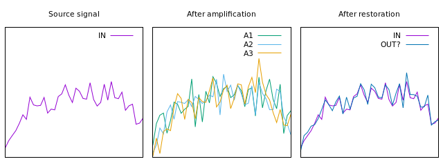
This answer mostly echo what everyone else has answered, but I took the time to illustrate how I believe it is designed to work.

You describe something like this:

schematic

simulate this circuit – Schematic created using CircuitLab

Each amplifier adds its own impurity, which is analyzed by the black box that restores the signal.

There are a number of problems with this idea.

The common mode amplifier will only amplify the portions of the signal found in all three s1, s2 and s3 and will reject any signal found only in one of these

The black box has no way of knowing which part of the signal is "in all" of the outputs and which is only in one. All of them will be different due to added noise. How to pick out the underlying signal?

A typical input signal (at least for audio) will look somewhat random. Look at this example:

enter image description here

The black box will see three signals that are different from each other. Assuming that each amplifier only adds uniformly random noise, the optimal way to remove this is by averaging. This will cancel out some of the noise, on average, but you still don't have the original signal. Your black box will also add noise to this, of course, after the averaging.

If your amplifiers are designed using the same principles using the same components, they will likely distort the signal in a very similar way. Your black box would not be able to do anything about that.

And no, noise and distortion can not be separated from "signal". You can't decide if a distorted guitar in a heavy metal song was already distorted before the amplifier or distorted by the amplifier. The same thing with noise. Sometimes I even listen to a music genre called noise.

\$\endgroup\$
0
\$\begingroup\$

given V1(f),V2(f),V3(f) which contain a common mode noise Vcm(f)

and -(V1(f)+V2(f)+V3(f) how can you isolate the Vcm(f)?

You can't.

Common Mode(CM) noise rejection is done in either or both of 2 ways.

  • Balancing both paths and impedances {of signal and return) so E and H field coupling is nulled over the noise spectrum of interest with some imbalance in differential mode impedance degrading this performance if return is ground.

  • raise the CM impedance Zcm(f) by at least a couple orders of magnitude and at the same time any signal imbalance becomes small compare to the CM impedance so the unbalanced differential signals become more balanced, where the signal return could be ground or a differential signal)

Since noise rejection of 60dB means an imbalance of 0.1% this easy to achieve with a CM choke, aka BALUN.

In both cases the induced Vcm is reduced to the Vcm*{Zs(f)/(Zs(f) + Zcm(f))} for each line and if balanced or Zcm >> Zs and/or ground then attenuation of common mode is far greater e.g. >>40 dB

A CM choke is balanced on each winding to very tight tolerances to give this balance. and the mutual inductance retains the same differential impedance.

THis is used everywhere noise is a problem on long lines like telephone, ethernet, data lines and even electret mics near SMPS without a ground and also used to reduce emissions in VGA, SMPS and stepper motors on long cables.

\$\endgroup\$
1
  • \$\begingroup\$ maybe you are thinking of audio voice cancellation methods where the singing is CM and the instruments are DM, then with 2 channels it is possible, but 3 no? \$\endgroup\$
    – D.A.S.
    Commented Jul 15, 2017 at 8:54

Your Answer

By clicking “Post Your Answer”, you agree to our terms of service and acknowledge you have read our privacy policy.

Not the answer you're looking for? Browse other questions tagged or ask your own question.