0
\$\begingroup\$

I am designing a linear translation stage that will be driven with a DC motor. When the circuit is powered the DC motor will start turning in either direction, which will move the linear stage towards one end. At that end the stage will activate limit switch #1 and the motor will turn the opposite direction until the stage activates limit switch #2. When limit switch #2 is activated the motor will turn in the original direction and send the stage back towards limit switch #1. This process will repeat until the circuit is powered off.

Does anyone have any ideas for how to build a circuit that reverses polarity to the motor using only a momentary pulse from a limit switch? I have built this circuit: Polarity Switching Circuit
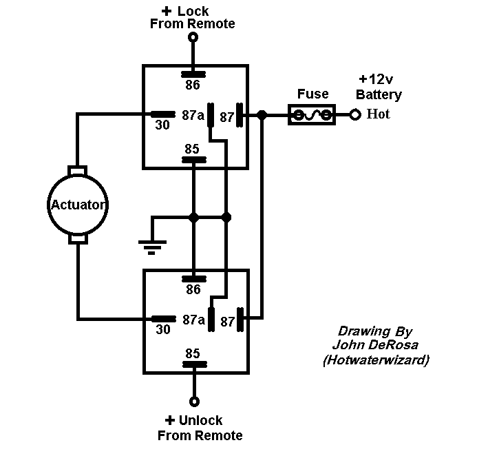
The circuit works great for its intended purpose, but it does not work for my needs because I need to be able to use momentary switches (limit switches). The circuit shown here will stop traveling as soon as the switch is released.

I have also tried to wire the circuit above through an Arduino. I used the momentary limit switches as inputs for interrupts. I had the same issue of the motor only moving while a switch was being actively closed. Here is the sketch that I came up with:

const int interruptPin = 2;

const int interruptPin2 = 3;

const int cwPin = 10;

const int ccwPin = 11;


void setup()
{

  pinMode(cwPin, OUTPUT);

  pinMode(ccwPin, OUTPUT);

  pinMode(interruptPin, INPUT);

  pinMode(interruptPin2, INPUT);

  attachInterrupt(0, goCw, RISING);

  attachInterrupt(1, goCcw, RISING);
}


void loop() 
{

digitalWrite(cwPin, HIGH);
}


void goCw()
{
 digitalWrite(cwPin, HIGH);
 digitalWrite(ccwPin, LOW);
}


void goCcw()
{
digitalWrite(cwPin, LOW);
digitalWrite(ccwPin, HIGH);
}

I would appreciate any advice that anyone has on this issue. I am open to using any method to achieve the desired outcome. I attempted to use the Arduino because I thought that it would solve my problem, but I am not against eliminating it if there is a better way.

\$\endgroup\$
1
  • \$\begingroup\$ Good first post. The diagram you posted is a wiring diagram and doesn't show the schema of your circuit. (We would have to look up the relay datasheets to figure out the contacts, etc., although I realise they are familiar to auto folks. There's a button for an easy to use schematic tool on the editor toolbar. \$\endgroup\$
    – Transistor
    Commented Jul 24, 2017 at 22:38

4 Answers 4

1
\$\begingroup\$

As for the arduino you can create a variable, say 'directionstatus' (yes long name abbreviate as required)

This is not code but rather the logic of operation - Create an IF statement in the loop to do the following:

If switch pressed
    If directionstatus = 1
    direction status =0
    ***Insert code to initiate one direction here***
    Else 
    directionstatus = 1
    ***Insert code to initiate other direction here*** 
    EndIf
EndIf

Then you can use either relays or mosfets or otherwise to operate the motor, and initiate the drive. If you want further elaboration please say.

It is possible to do without an arduino but you seem to have one already there and useful and potentially ready to go.

Added benefit of using a uC is if you know the speed and implement some timings etc you could control travel, and if you move to stepper motors later on (not sure if your application requires) you can have very precise control quite easily - but for now I would imagine an If in void_loop that operates when button is pressed would suffice.

... P.S.

Just thought - please have a look at this as this might be upset your code later on as each time the switch is initiated it may bounce, plus you might find it triggers when it actuates and triggers when you leave (in which case update code to ignore every second instruction) https://www.arduino.cc/en/Tutorial/Debounce

\$\endgroup\$
0
\$\begingroup\$

I would use a H-bridge circuit. For example, L293 could be a good starting point. This circuit not only lets you drive the load (DC motor) but also lets you control the direction of the motor in an easy way.

Before the H-bridge block you could use either arduino logic or use another circuit (like a counter) in which the inputs are the limit switches and the output is the control signal for the bridge direction.

Hope this helps.

\$\endgroup\$
0
\$\begingroup\$

schematic

simulate this circuit – Schematic created using CircuitLab

Figure 1. Hard-wired motor reverser.

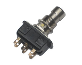
Depending on the power of your drive, the double-pole, double-throw footswitch beloved of guitarists the world over for stomp-box effects units may suit.

How it works:

Each press of SW1 or SW2 will reverse the polarity of the motor supply. The switches should be positioned at each end of travel to be depressed by the moving stage.

enter image description here

Figure 2. A double-pole double-throw (DPDT) footswitch.

The Arduino should be programmed to blink LEDs so it looks like a complicated control system.

\$\endgroup\$
0
\$\begingroup\$

This can be done with one DPDT impulse (latching) relay. Both limit switches are wired on parallel, in series with the relay coil, battery, and GND. The relay contacts are wired in a standard DC reversing arrangement. When either switch is touched, the relay changes state and the motor reverses.

I don't see a way to attach a PDF datasheet. Here is a link to details at Digi-Key: https://www.digikey.com/product-detail/en/te-connectivity-potter-brumfield-relays/S89R11DAC1-12/PB513-ND/365946

\$\endgroup\$
3
  • 1
    \$\begingroup\$ Welcome to EE.SE. There's a button for an easy to use schematic tool on the editor toolbar. Schematic trumps words. \$\endgroup\$
    – Transistor
    Commented Jul 24, 2017 at 22:39
  • \$\begingroup\$ I don't want to upload a schematic, just a datasheet. But if I did want to post a circuit, uploading a graphic of my own schematic trumps learning another schematic tool. \$\endgroup\$
    – AnalogKid
    Commented Jul 26, 2017 at 11:55
  • 1
    \$\begingroup\$ Actually the PDF it makes your answer closer to a "link-only" answer and these are discouraged as the answer becomes useless when the link dies. (See the Help Center for more on this.) At least you have provided some other text but I would be hard pressed to draw the circuit based on your text. I encourage you to upload your own schematic. \$\endgroup\$
    – Transistor
    Commented Jul 26, 2017 at 12:01

Your Answer

By clicking “Post Your Answer”, you agree to our terms of service and acknowledge you have read our privacy policy.

Not the answer you're looking for? Browse other questions tagged or ask your own question.